永久磁石同期モーター (PMSM)
これらの参照例は、従来の手法から高度な手法まで、PMSM 用のセンサーベースおよびセンサーレスのモーター制御アルゴリズムの実装に使用します。
注目の例

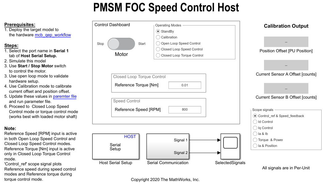
開ループ制御での三相 AC モーターの駆動と ADC オフセットのキャリブレーション
この例では、開ループ制御 (スカラー制御またはボルト/ヘルツ制御とも呼ばれる) を使用してモーターを駆動します。この手法では、モーターからのいずれのフィードバックも使用せずに、固定子電圧と周波数を変えて回転子速度を制御します。この手法を使用してハードウェア接続の整合性を確認できます。開ループ制御の一定速度のアプリケーションでは、固定周波数のモーター電源を使用します。開ループ制御の可変速度のアプリケーションでは、回転子速度を制御するために可変周波数の電源が必要です。固定子の磁束を一定に保つために、電源電圧の振幅がその周波数と比例するように維持します。

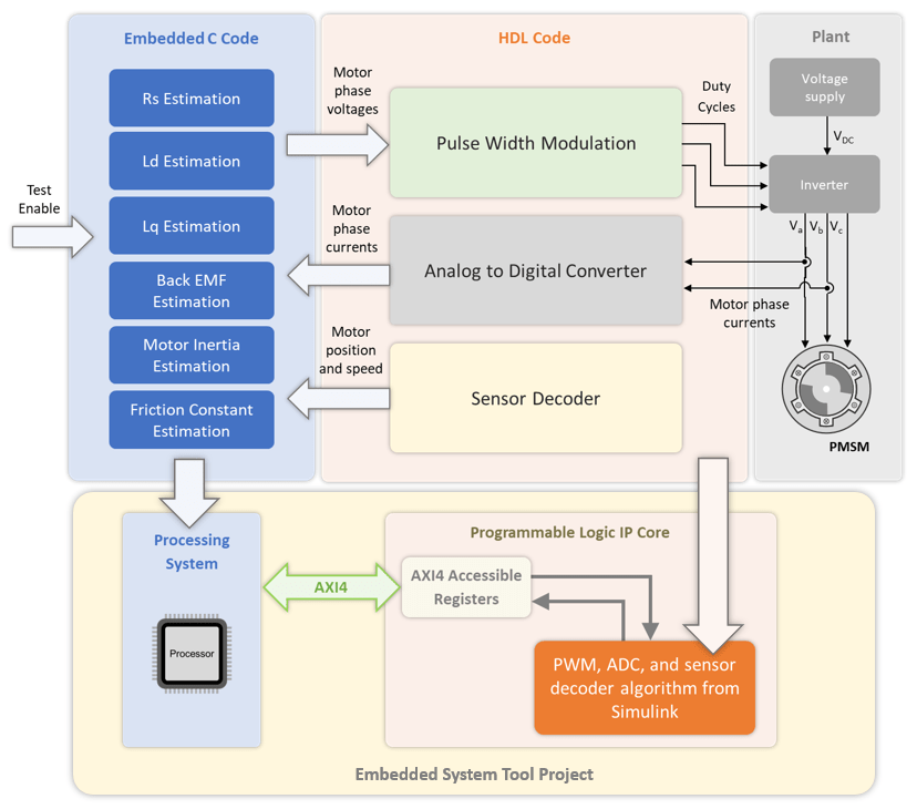
Estimate PMSM Parameters Using Custom Hardware
Includes an algorithm to determine the parameters of a permanent magnet synchronous motor (PMSM) using any custom motor-control hardware (hardware not used in the Motor Control Blockset™ examples). The algorithm determines these parameters:
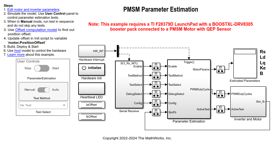
Estimate PMSM Parameters Using Parameter Estimation Blocks
Uses the parameter estimation blocks provided by Motor Control Blockset™ to estimate these parameters of a permanent magnet synchronous motor (PMSM) with a quadrature encoder sensor:
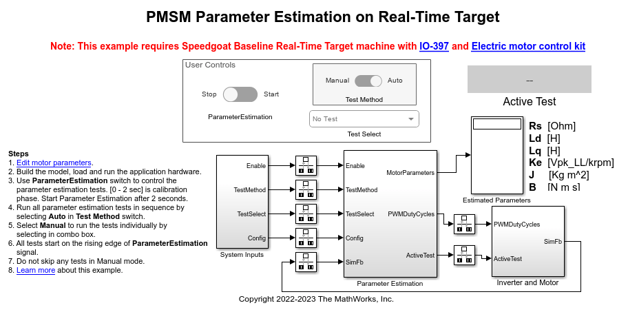
Estimate PMSM Parameters Using Parameter Estimation Blocks on Real-Time Systems
Uses the parameter estimation blocks provided by Motor Control Blockset™ to estimate these parameters of a permanent magnet synchronous motor (PMSM):
Estimate PMSM Parameters Using FPGA-Based Motor Control Development Kit
Estimate parameters of a permanent magnet synchronous motor (PMSM) using blocks from Motor Control Blockset™ on an FPGA device (Trenz Electronic™ Motor Control Development Kit TE0820).

PMSM のセンサーレス ベクトル制御
この例では、三相永久磁石同期モーター (PMSM) の角速度を制御するためのベクトル制御 (FOC) 手法を実装します。FOC の詳細については、ベクトル制御を参照してください。

Hall Offset Calibration for PMSM
Calculates the offset between the rotor direct axis (d-axis) and position detected by the Hall sensor. The field-oriented control (FOC) algorithm needs this position offset to run the permanent magnet synchronous motor (PMSM) correctly. To compute the offset, the target model runs the motor in the open-loop condition. The model uses a constant (voltage along the stator's
d-axis) and a zero (voltage along the stator's
q-axis) to run the motor (at a low constant speed) by using a position or ramp generator. When the position or ramp value reaches zero, the corresponding rotor position is the offset value for the Hall sensors.

ホール センサーを使用した PMSM のベクトル制御
この例では、三相永久磁石同期モーター (PMSM) の角速度を制御するためのベクトル制御 (FOC) 手法を実装します。この FOC アルゴリズムには回転子の位置フィードバックが必要であり、それをホール センサーで取得します。FOC の詳細については、ベクトル制御を参照してください。

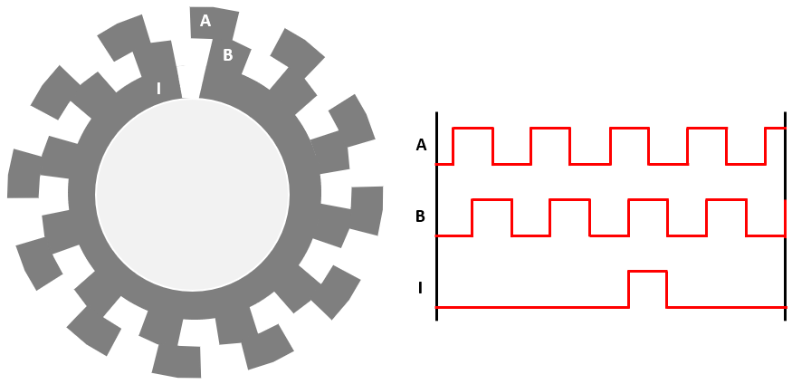
Quadrature Encoder Offset Calibration for PMSM
Calculates the offset between the d-axis of the rotor and encoder index pulse position as detected by the quadrature encoder sensor. The control algorithm (available in the field-oriented control and parameter estimation examples) uses this offset value to compute an accurate and precise position of the d-axis of rotor. The controller needs this position to implement the field-oriented control (FOC) correctly in the rotor flux reference frame (d-q reference frame), and therefore, run the permanent magnet synchronous motor (PMSM) correctly.
直交エンコーダーを使用した PMSM のベクトル制御
この例では、三相永久磁石同期モーター (PMSM) の角速度を制御するためのベクトル制御 (FOC) 手法を実装します。この FOC アルゴリズムには回転子の位置フィードバックが必要であり、それを直交エンコーダー センサーで取得します。FOC の詳細については、ベクトル制御を参照してください。

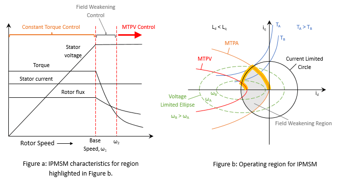
PMSM の弱め界磁制御 (MTPA を使用)
この例では、三相永久磁石同期モーター (PMSM) のトルクと角速度を制御するためのベクトル制御 (FOC) 手法を実装します。この FOC アルゴリズムには回転子の位置フィードバックが必要であり、それを直交エンコーダー センサーで取得します。FOC の詳細については、ベクトル制御を参照してください。
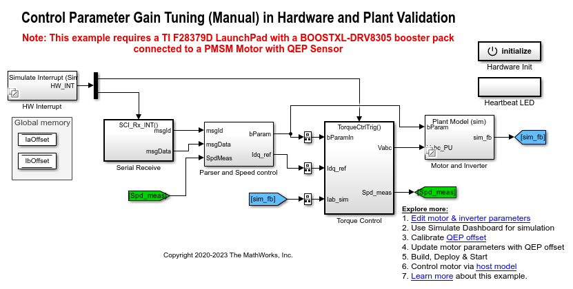
Tune Control Parameter Gains in Hardware and Validate Plant
Uses field-oriented control (FOC) to run a three-phase permanent magnet synchronous motor (PMSM) in different modes of operation for plant validation. FOC algorithm implementation needs the real-time feedback of the rotor position. This example uses a quadrature encoder sensor to measure the rotor position. For details about FOC, see ベクトル制御.

SI 単位を使用した PMSM のベクトル制御
この例では、三相永久磁石同期モーター (PMSM) の角速度を制御するためのベクトル制御 (FOC) 手法を実装します。ただし、この例の FOC アルゴリズムでは、pu 表現の数量の代わりに (pu 単位系の詳細についてはPer-Unit Systemを参照)、SI 単位の信号を使用して計算を実行します。それらの信号とその SI 単位は次のとおりです。
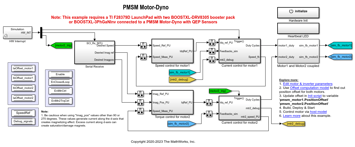
Control PMSM Loaded with Dual Motor (Dyno)
Uses field-oriented control (FOC) to control two three-phase permanent magnet synchronous motors (PMSM) coupled in a dyno setup. Motor 1 runs in the closed-loop speed control mode. Motor 2 runs in the torque control mode and loads Motor 1 because they are mechanically coupled. You can use this example to test a motor in different load conditions.
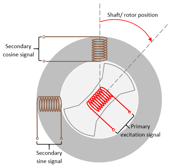
Monitor Resolver Using Serial Communication
Use the resolver sensor to measure the rotor position. The resolver consists of two stator (secondary) windings placed orthogonally around the resolver rotor (primary) winding. After you mount the resolver sensor over a PMSM, the resolver rotor winding rotates with the shaft of the running motor. Meanwhile, the controller provides a fixed-frequency excitation signal (alternating sinusoidal or square pulse) to the primary winding.

Simscape Electrical を使用したインバーターのスイッチング ダイナミクスのモデル化
この例では、ベクトル制御 (FOC) を使用して三相永久磁石同期モーター (PMSM) の角速度を制御します。Motor Control Blockset™ の Average Value Inverter ブロックの代わりに次の Simscape™ Electrical™ ブロックを使用するオプションが用意されています。

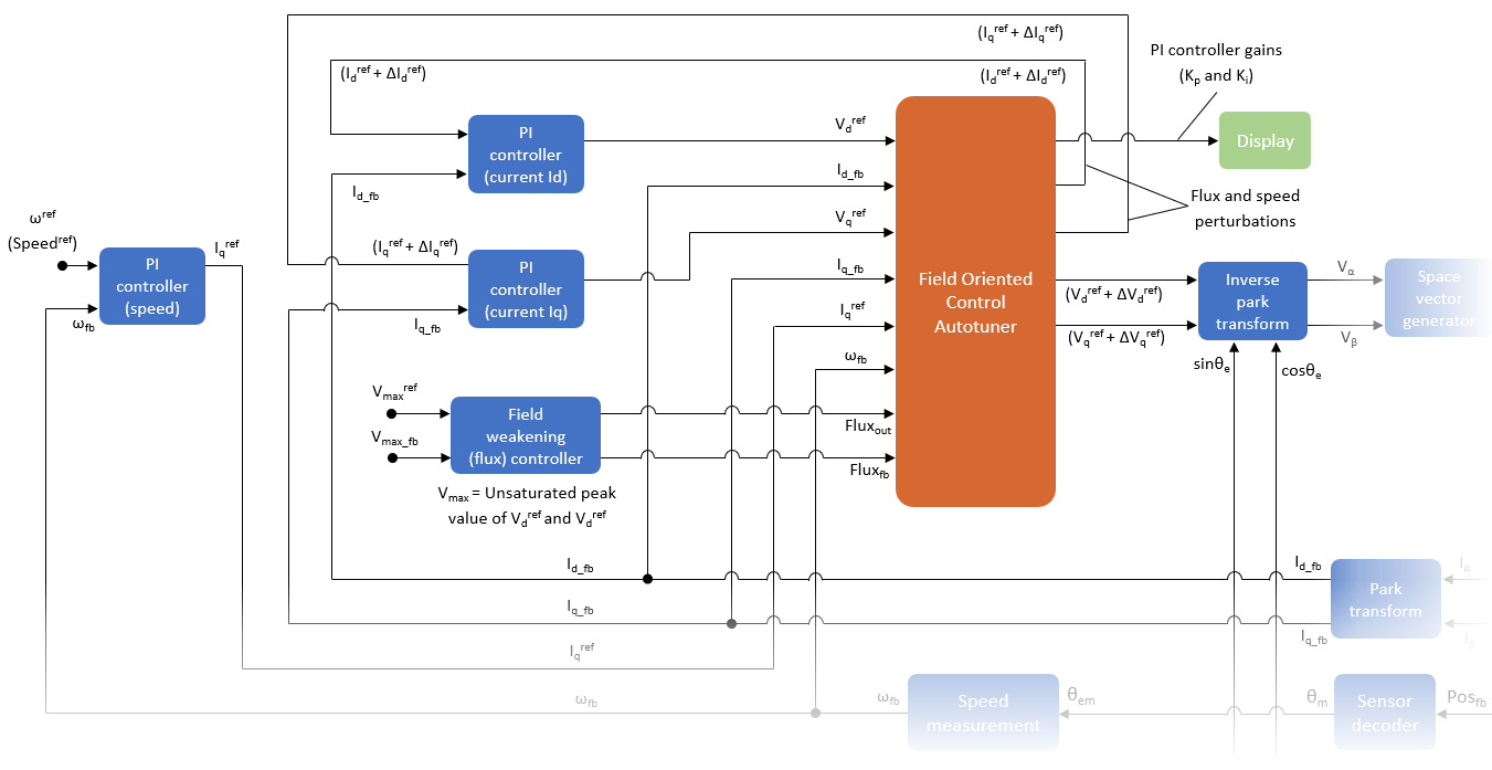
Tune PI Controllers Using Field Oriented Control Autotuner
Computes the gain values of PI controllers available in the speed and current control loops by using the Field Oriented Control Autotuner block. For details about this block, see Field Oriented Control Autotuner. For details about field-oriented control, see ベクトル制御.
Tune PI Controllers (in Field-Weakening Control Mode) Using FOC Autotuner Block
Uses the Field Oriented Control Autotuner block to compute the gain values of the PI controllers available in the speed, current, and flux control loops of a field-weakening control algorithm. For details about this block, see Field Oriented Control Autotuner.

Tune PI Controllers Using Field Oriented Control Autotuner Block on Real-Time Systems
Compute the gain values of PI controllers within the speed and current controllers by using the Field Oriented Control Autotuner block.

Position Control of PMSM Using Quadrature Encoder
Implements the field-oriented control (FOC) technique to control the position of a three-phase permanent magnet synchronous motor (PMSM). The FOC algorithm requires rotor position feedback, which it obtains from a quadrature encoder sensor.
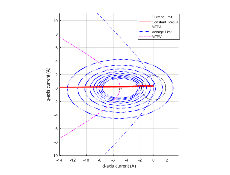
PMSM Drive Characteristics and Constraint Curves
Uses Motor Control Blockset™ to show how to use the PMSM characteristic plotting and PMSM milestone speed identification functions to obtain a control trajectory.
MATLAB Project for FOC of PMSM with Quadrature Encoder
This MATLAB® project provides a motor control example model that uses field-oriented control (FOC) to run a three-phase permanent magnet synchronous motor (PMSM) in different modes of operation. Implementing the FOC algorithm needs real-time rotor position feedback. This example uses a quadrature encoder sensor to measure the rotor position. For details about FOC, see ベクトル制御.

Frequency Response Estimation of PMSM Using Field-Oriented Control
Performs frequency response estimation (FRE) of a plant model running a three-phase permanent magnet synchronous motor (PMSM). When you simulate or run the model on the target hardware, the model runs tests to estimate the frequency response as seen by each PI controller (also known as raw FRE data) and plots the FRE data to provide a graphical representation of the plant model dynamics.

Integrate MCU Scheduling and Peripherals in Motor Control Application
Identify and resolve issues with respect to peripheral settings and task scheduling early during development.

Partition Motor Control for Multiprocessor MCUs
Partition real-time motor control application on to multiple processors to achieve design modularity and improved control performance.

Estimate Initial Rotor Position Using Pulsating High-Frequency and Dual-Pulse Methods
Estimates the initial position (in electrical radians) of a stationary interior PMSM by using pulsating high-frequency (PHF) injection and dual pulse (DP) techniques.

Algorithm-Export Workflows for Custom Hardware
Enables you to use any custom motor-control hardware (hardware not used in the Motor Control Blockset™ examples) to run a three-phase permanent magnet synchronous motor (PMSM) using field-oriented control (FOC). Using the algorithm export workflows, which involve generating code for the control algorithm by using Simulink® and Embedded Coder® and then integrating it with either manually written or externally generated hardware driver code. This example explains the algorithm export workflows along with the intermediate steps.
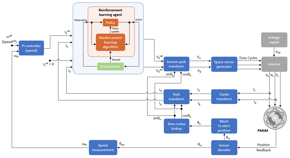
強化学習を使用した PMSM のベクトル制御
この例では、強化学習の制御設計法を使用して永久磁石同期モーター (PMSM) のベクトル制御 (FOC) を実装する方法を示します。この例では FOC の原理を使用します。ただし、PI コントローラーの代わりに強化学習 (RL) エージェントを使用します。FOC の詳細については、ベクトル制御を参照してください。

Field-Oriented Control (FOC) of PMSM Using Hardware-in-the-Loop (HIL) Simulation
Uses hardware-in-the-loop (HIL) simulation to implement the field-oriented control (FOC) algorithm to control the speed of a three-phase permanent magnet synchronous motor (PMSM). The FOC algorithm requires rotor position feedback, which is obtained by a quadrature encoder sensor. For more information on FOC, see ベクトル制御.

Direct Torque Control of PMSM Using Quadrature Encoder or Sensorless Flux Observer
Implements direct torque control (DTC) technique to control the speed of a three-phase permanent magnet synchronous motor (PMSM). Direct Torque Control (DTC) is a vector motor control technique that implements motor speed control by directly controlling the flux and torque of the motor. The example algorithm needs motor currents and position feedback from PMSM. It uses space vector pulse-width modulation (DTC-SVPWM) variant of DTC, which uses space vector modulation (SVM) to produce the pulse-width modulation (PWM) duty cycles that are used by the inverter. For more details about the DTC-SVPWM algorithm used in this example, see 直接トルク制御 (DTC).

Determine Power Losses and THD for PWM Methods
Calculates the inverter power loss and total harmonic distortion (THD) in motor current for different pulse-width modulation (PWM) methods. The example uses field-oriented control (FOC) algorithm that runs a permanent-magnet synchronous motor (PMSM) in speed control mode as a reference. The example only supports simulation.
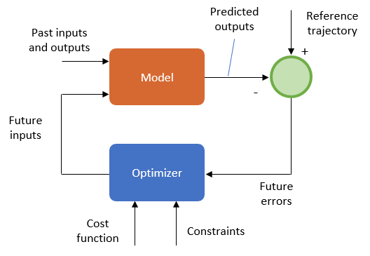
Run Field Oriented Control of PMSM Using Model Predictive Control
Uses Model Predictive Control (MPC) to control the speed of a three-phase permanent magnet synchronous motor (PMSM).

FOC of PMSM Using FPGA-Based Motor Control Development Kit
Use a Field-Oriented Control (FOC) algorithm for a Permanent Magnet Synchronous Motor (PMSM) by using blocks from the Motor Control Blockset™ on an FPGA device (Trenz Electronic™ Motor Control Development Kit TE0820).

PIL テストを使用したコードの検証とプロファイリング
この例では、Texas Instruments® LAUNCHXL-F28379D ハードウェア ボードでの PIL プロファイリングについて説明します。プロセッサインザループ (PIL) シミュレーションでは、制御アルゴリズムはターゲット ハードウェアで実行されますが、プラント モデルはホスト マシンで実行されます。プラント モデルは、コントローラーに対する入力信号と出力信号をシミュレートし、シリアル通信インターフェイスを使用してコントローラーと通信します。この機能により、PIL シミュレーションを使用してターゲット ハードウェアでの実行時間を特定し、ホスト マシンでモデルをシミュレートする実行時間と比較できます。
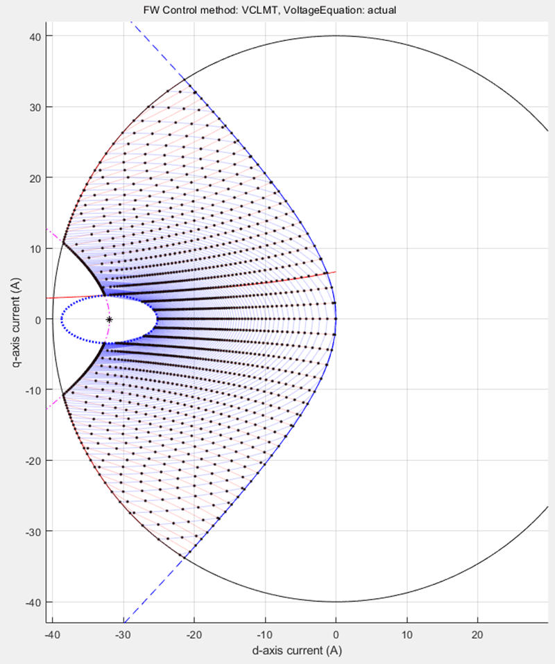
Field-Weakening Control (with MTPA) of Nonlinear PMSM Using Lookup Table
Uses a lookup table (LUT) for a nonlinear permanent magnet synchronous motor (PMSM) and controller to run the motor using field-weakening control (with maximum torque per ampere (MTPA)). Use this example to replicate and run a finite element analysis (FEA) based nonlinear, high-fidelity PMSM in simulation. This example helps motor design engineers to simulate high-performance motors in real-world motor control applications. In addition, control system engineers can use this example to design control algorithms for a given set of motor parameter data to achieve high levels of accuracy in tracking and controlling speed and torque as well as to meet efficiency requirements, especially for high-performance motors.
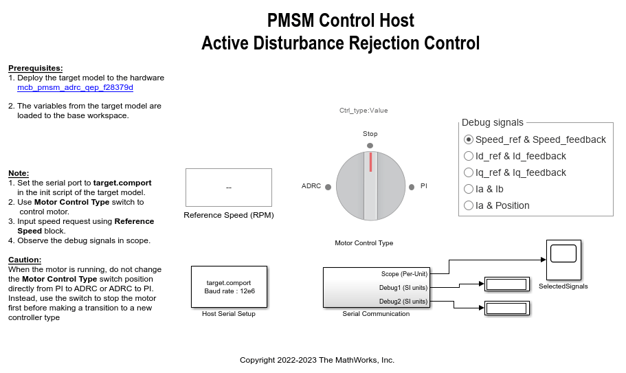
Implement PMSM Speed Control Using Active Disturbance Rejection Control
Implement active disturbance rejection control (ADRC) of the speed of a permanent magnet synchronous motor (PMSM) modeled in Simulink® using the Active Disturbance Rejection Control (Simulink Control Design) block. You can use the example to implement field-oriented control (FOC) using either a proportional integral (PI) or ADRC-based controller to run the motor in the speed control mode. Therefore, you can compare the performance of the PI and ADRC controllers.
PMSM Constraint Curves and Their Application
Uses Motor Control Blockset™ to explain the fundamentals of constraint curves, utilization of these curves to determine operating currents, and usage of the grid of these currents in simulation or deployment environments.

Implement Field-Oriented Control on FPGA SoC
Deploy a field-oriented control (FOC) algorithm for brushless DC motors to an SoC device by using a custom board target. A custom board target for the Trenz Electronic™ Motor Control Development Kit, based on Xilinx® Zynq® UltraScale+ MPSoC, allows you to deploy FOC application as a mix of software to the ARM® Cortex-A processor and hardware to the programmable logic of the device. This example uses the model and control algorithm partitioning from the Hardware-Software Partitioning of a Motor Control Algorithm (SoC Blockset) example.

Swap Motors with Single Model Deployment of Sensor-Based FOC Algorithm
Run a permanent magnet synchronous motor (PMSM) in an industrial drive application setup using position-sensor-based field-oriented control (FOC). Industrial drives enable you to swap motors in real-time without repeated deployment of code. An industrial drive setup needs a fixed inverter and software that has the ability to adapt the control algorithm according to the new motor using only the updated nameplate parameters.
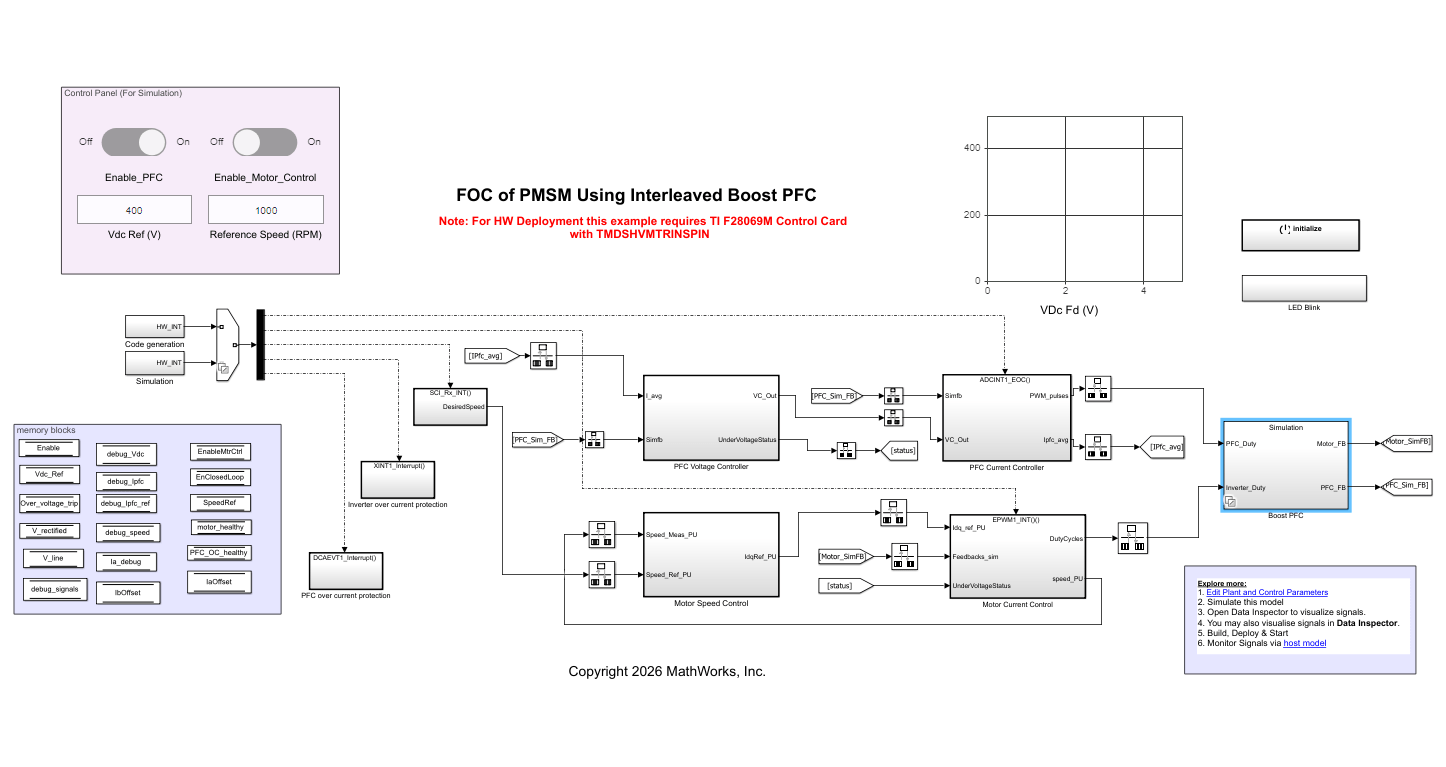
Field Oriented Control of PMSM Using Interleaved Boost Power Factor Correction
Implement field oriented control of PMSM with input power factor correction.
Swap Motors with Single Deployment of Sensorless FOC Algorithm
Run a permanent magnet synchronous motor (PMSM) in an industrial drive application setup using a sensorless field-oriented control (FOC) algorithm. The example uses a sensorless Flux Observer to estimate the motor position. Industrial drives enable you to replace a motor with a new one without repeated deployment of code. An industrial drive setup needs only nameplate parameters to adapt the software to the new motor.

Initial Position Estimation and Field-Weakening Control of IPMSM Using Pulsating High-Frequency Injection and Extended EMF Observer
Uses sensorless techniques such as pulsating high-frequency injection and extended EMF observer to estimate and track motor position to run an interior permanent magnet synchronous motor (IPMSM) operation using field-weakening control (FWC).

Generate Motor Control Models for Selected Algorithm and Hardware
Use Motor Control Blockset™ to generate a Simulink® model that is configured for a specific hardware and motor control technique.
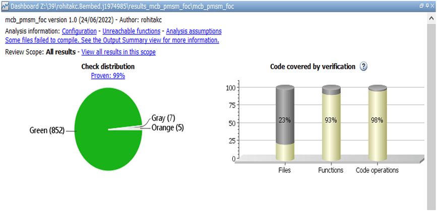
Analyze and Verify Motor Control Algorithms Using Polyspace
Uses the Polyspace® static code analysis tools to analyze and verify Simulink® models containing motor control algorithms. Static code analysis is a software verification technique that analyzes source code for quality, reliability, and security without executing the code. This approach uses robust error detection routines (that include checks for critical run-time errors) to identify bugs and defects and in addition ensures compliance with common coding standards. It provides a cost-effective alternative to measure and track the software quality metrics and eliminates the need to instrument the code or to write elaborate unit test cases.
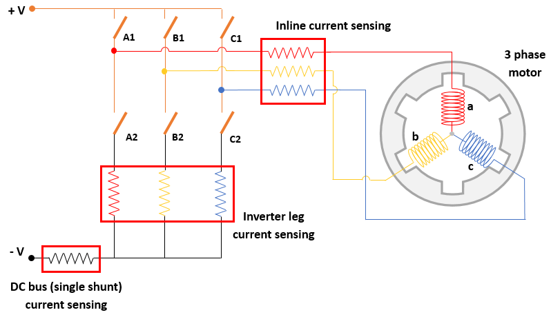
Sensorless Field-Oriented Control of PMSM Using DC Shunt Current Sensing
Implement sensorless field-oriented control (FOC) using only a single DC bus-based current measurement to run a permanent magnet synchronous motor (PMSM).

Sensorless Field-Oriented Control of PMSM Using I-F Control-Based Startup
Implements field-oriented control (FOC) using sensorless position estimation and I-F control-based startup to control the speed of a three-phase permanent magnet synchronous motor (PMSM).

AUTOSAR-Based FOC of PMSM
Implement an AUTOSAR-based field-oriented control (FOC) algorithm to run a permanent magnet synchronous motor (PMSM).

Field-Oriented Control of PMSM Using Position Estimated by Neural Network
Implement field-oriented control (FOC) of a permanent magnet synchronous motor (PMSM) using a rotor position estimated by an autoregressive neural network (ARNN) trained with Deep Learning Toolbox™.
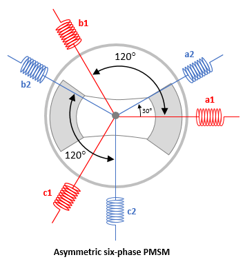
Field-Oriented Control of Six-Phase PMSM
Control the torque of an asymmetric six-phase permanent magnet synchronous motor (PMSM) using field-oriented control (FOC).
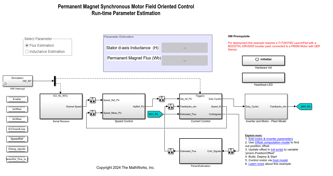
Run-Time Parameter Estimation of PMSM Using Sensor Feedback
Estimate the parameters of a permanent magnet synchronous motor (PMSM) at run-time. The example estimates the following PMSM parameters by running tests while the motor runs using a closed-loop field-oriented control (FOC) algorithm:
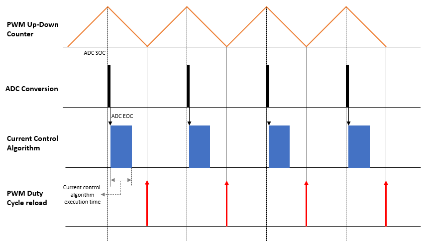
Motor Control Architectures Based on Different Current Sampling and PWM Frequencies
Enables you to implement different motor control architectures that use non-identical sampling rates for ADC conversion, PWM, and current controller algorithm to run a permanent magnet synchronous motor (PMSM) using field-oriented control (FOC).

Obtain Controller Gains to Run Motor Using Field-Oriented Control
Obtain PI controller gains using Optimum theory for the current control loop and speed control loop in Field Oriented Control (FOC) of a Permanent Magnet Synchronous Motor (PMSM). This example provides multiple options that you can use to obtain PI controller gains:
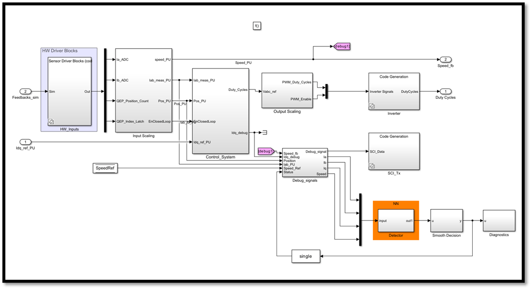
Detect Unbalanced Motor by Using Neural Network
Detect a mechanically unbalanced spinning motor by using a neural network (NN) developed using Deep Learning Toolbox™.