このページの内容は最新ではありません。最新版の英語を参照するには、ここをクリックします。
テスト ハーネスとパラメーター化
このセクションでは、複数の Simscape Fluids ドメインにおけるテスト ハーネスまたはパラメーター化の例を確認できます。
注目の例
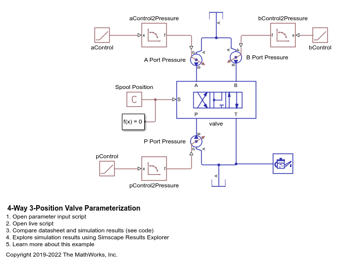
4 方向 3 位置バルブのパラメーター化
この例では、テスト ハーネスを使用して 4 方向 3 位置バルブのパラメーター化とテストを行う方法を示します。ブロックとデータの出流量を比較してテスト ハーネスを検証するために、この例にはプロット スクリプトが用意されています。また、パラメーター化とテスト ハーネス ワークフローについて詳しく説明するために、この例ではライブ スクリプトも提供されています。
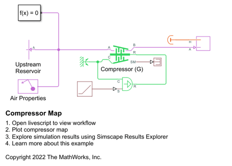
圧縮機マップ
この例では、動的圧縮機の性能特性を指定するために必要な圧力比、補正済み質量流量、および効率のテーブルを作成する方法を示します。

凝縮器および蒸発器の熱伝達
この例では、冷媒 R134a が左側に、湿り空気が右側にある簡単なテスト セットアップで凝縮器または蒸発器をモデル化します。冷媒で満たされたチューブ バンクを湿り空気が通る直交流配置となっています。
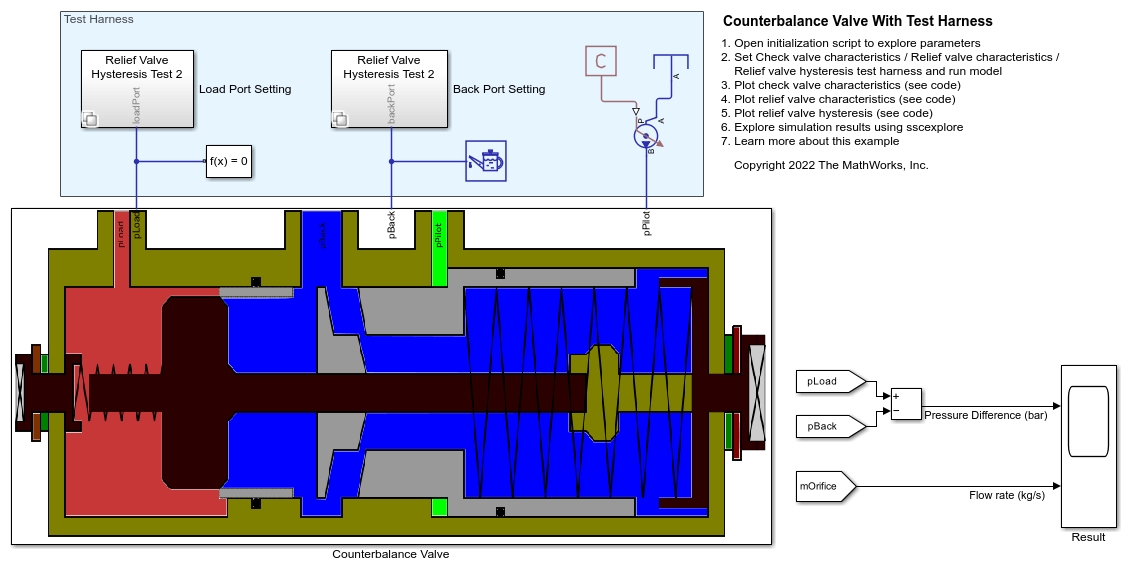
Counterbalance Valve with Test Harness
Model, parameterize, and test a counterbalance valve in detailed fidelity and system level fidelity using a variant subsystem. Running the model generates a plot of the flow from the load port to the back port due to the relief action of the counterbalance valve using the detailed fidelity variant. A counterbalance valve allows an upstream flow from the back port to the load port through the check valve stage, and it allows a downstream flow from the load port to the back port through the relief stage. Counterbalance valves help with load holding, load actuation speed control, and safety.

Cylinder Linearization
Linearize a Simscape™ hydro-mechanical system model to check stability of an open-loop system around an operating point. This example uses the Simulink Control Design™ Frequency Response Estimator block to perform a frequency response estimation experiment and store the data for later estimation offline.

Cylinder Design Parameter Estimation
Parameterize and test a tandem primary cylinder starting from a manufacturer datasheet. This example uses optimization to determine remaining unknown parameters, given the numerical data extracted from the datasheet. After the model is simulated, it compares the resulting push rod force - brake pressure relationship curve to the curve provided on the manufacturer datasheet. Understanding the behavior of the tandem primary cylinder is important when selecting other braking system components.

Cylinder Design Parameter Sensitivity Analysis
Perform a sensitivity analysis for tandem primary cylinder model in Simscape™. The example requires the Simulink® Design Optimization™ to be installed and licensed to run.
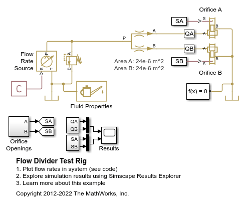
Flow Divider Test Rig
Warning: This example uses the hydraulic domain, which will be removed in a future release. Find an equivalent example model that uses the isothermal liquid domain here: 分流器. To convert models to the isothermal liquid domain, use the hydraulicToIsothermalLiquid tool.
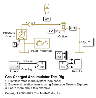
Gas-Charged Accumulator Test Rig
A test rig for the Gas-Charged Accumulator (IL) block. The pressure source with the orifice closed charges the accumulator. The check valve holds the accumulator at its charged pressure, and as the orifice opens the accumulator discharges.
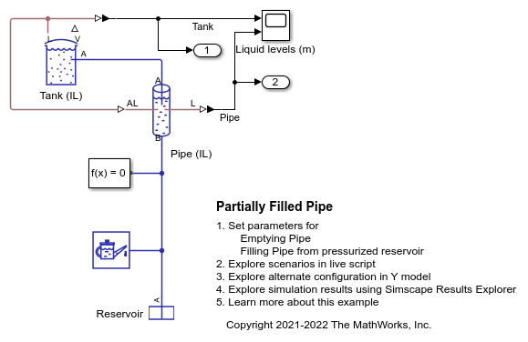
部分充填パイプ
この例では、タンクの排出と充填をモデル化するために複数の構成で使用される Partially Filled Pipe (IL) ブロックを示します。この例で用意されているライブ スクリプトを使用して、さまざまな構成の効果を理解できます。
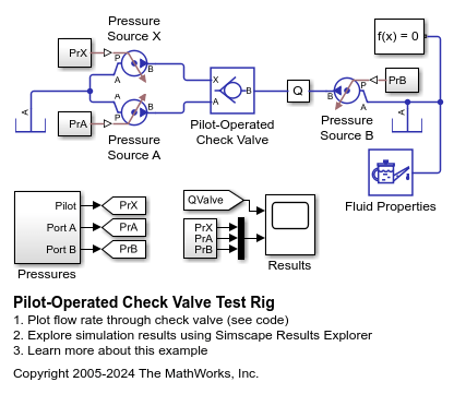
パイロット操作チェック バルブの試験リグ
この例では、Pilot-Operated Check Valve (IL)ブロックの試験リグを示します。バルブは 3 つの理想的な圧力源に接続されています。そのうちの 2 つでメインの流線全体の圧力差を作成し、3 つ目でパイロット端子 "X" に圧力を適用します。この圧力により、メインの圧力差が負の場合でも流量がバルブを通過します。
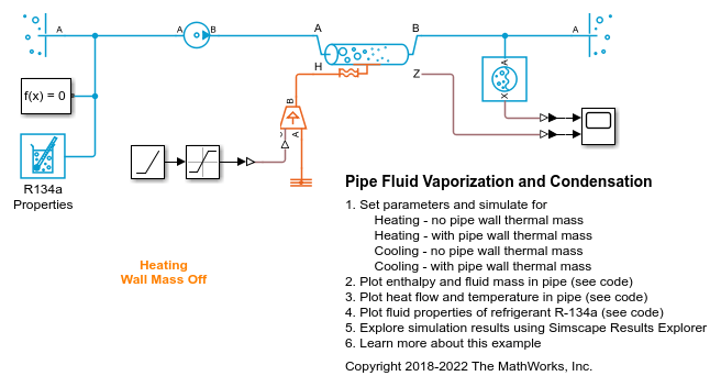
パイプの流体の蒸発と凝縮
この例では、パイプ内の流体の蒸発と凝縮をモデル化するために使用される 3-Zone Pipe (2P) ブロックを示します。このブロックは、パイプを流れる流体の状態に応じて、内部の流体体積を液体領域、混合体領域、蒸気領域の最大 3 つの領域に分割します。流体がパイプ内を流れるにつれて、パイプ外部の環境とパイプ内部の流体の間で熱が伝達され、加熱の場合は液体、混合体、蒸気の順、冷却の場合は蒸気、混合体、液体の順に流体が変化します。オプションとして、非ゼロのパイプ肉厚を指定することでパイプ壁面の蓄熱効果をオンにできます。
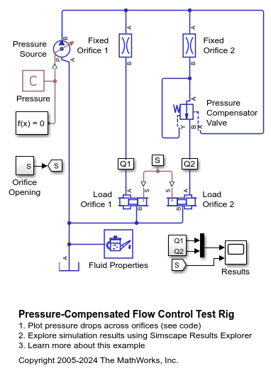
圧力補償流量制御の試験リグ
この例では、Pressure Compensator Valve (IL)ブロックの試験リグを示します。定圧力源に接続された 2 つの流路のそれぞれに、固定オリフィスと、可変負荷として機能する可変オリフィスがあります。一方の流路に圧力補償バルブが含まれています。
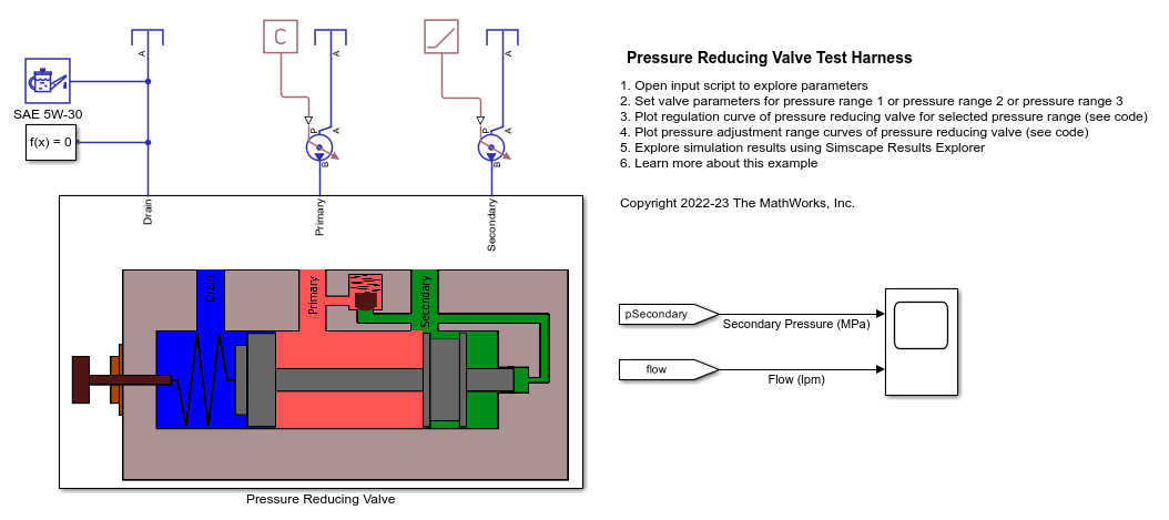
Pressure Reducing Valve Test Harness
Model, parameterize, and test a pressure reducing valve. The model is used to generate a plot of the regulation curve i.e. a plot of flow vs regulated pressure. This plot can be compared with the characteristics from the manufacturer datasheet to verify the test harness. The regulation curve displays two valve functions namely the reducing function and the relieving function. The reducing valve remains open when the pressure at the secondary port is less than a specified pressure, known as the set pressure. When the pressure at the secondary port meets or surpasses the set pressure, the reducing valve closes. In the regulation curve, the region of positive flow represents the phase when the reducing valve is open and gradually closes. The pressure reducing valve used in this example has a check valve that relieves pressure when the secondary pressure is about to surpass the set pressure. During this phase, the hydraulic fluid escapes via the check valve to the primary port keeping the secondary pressure constant at the set pressure. The region of negative flow in the regulation curve represents the phase when the pressure reducing valve is closed and the check valve opens gradually. Pressure reducing valves are used in industry to limit and maintain pressure during operations like hydraulic pressing, punching, drilling and stamping.

Pressure Relief Valve Test Rig
A test rig to check the pressure-flow characteristic of the Pressure Relief Valve (IL) block. A pressure relief valve and a variable orifice connect to a constant flow rate source in parallel. As the orifice closes, pressure gradually builds up and eventually reaches the set pressure differential of the pressure relief valve. At this pressure, the valve begins to divert flow to the tank and regulates the pressure at the source outlet. As the orifice opens again, the pressure relief valve closes and the entire flow passes through the variable orifice.

Receiver Accumulator
The liquid and vapor separation using the Receiver Accumulator (2P) block. The Receiver Accumulator (2P) block models a container of fluid in a two-phase fluid network with separate liquid and vapor ports. In an HVAC system, when this tank is placed between a condenser and an expansion valve, it acts as a receiver. Liquid connections to the block are made at ports AL and BL. When the tank is placed between an evaporator and a compressor, it acts as an accumulator. Vapor connections to the block are made at ports AV and BV. The fluid in the container can be fully liquid, fully vapor, or a mixture of both. Mass and energy exchange can occur between the fluid phases due to vaporization and condensation.
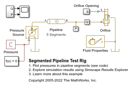
Segmented Pipeline Test Rig
Warning: This example uses the hydraulic domain, which will be removed in a future release. Find an equivalent example model that uses the isothermal liquid domain here: ウォーター ハンマー現象. To convert models to the isothermal liquid domain, use the hydraulicToIsothermalLiquid tool.
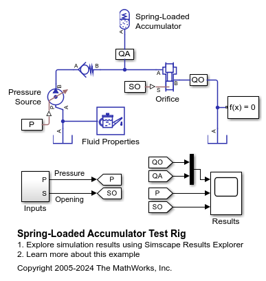
バネ式アキュムレータの試験リグ
この例では、Spring-Loaded Accumulator (IL)ブロックの試験リグを示します。オリフィスが閉じているときは、圧力源からアキュムレータに圧力が充填されます。アキュムレータの充填圧力がチェック バルブによって維持され、オリフィスが開くとアキュムレータから放出されます。