このページは機械翻訳を使用して翻訳されました。最新版の英語を参照するには、ここをクリックします。
HDL Verifier からの Microchip FPGA ボード サポート
HDL Verifier™ は、FPGA ボードと Simulink® または MATLAB® のシミュレーション間の接続を提供することで、FPGA ボード上の HDL コードの検証を自動化します。
FPGA インザループ (FIL) を使用すると、FPGA ボード上で実行されている HDL 設計と同期された Simulink または MATLAB シミュレーションを実行できます。
FPGA インザループを使用するには、サポートされている接続タイプを使用して MATLAB ホスト コンピューターに接続されたサポートされている FPGA ボードと、サポートされている合成ツールが必要です。
メモ
HDL Verifier Microchip FPGA ボード用サポート パッケージ はボードのカスタマイズをサポートしていません。
サポートされている Microchip FPGA ボード
このサポート パッケージにより、表内のボードの FPGA インザループ シミュレーションが可能になります。
| デバイス ファミリ | ボード | イーサネット | JTAG | PCIエクスプレス | コメント |
|---|---|---|---|---|---|
マイクロチップ SmartFusion® 2 | マイクロチップ SmartFusion 2 SoC FPGA アドバンス開発キット | X | Microchip SmartFusion 2 SoC FPGA アドバンスト開発キットのインストールを参照してください。 | ||
マイクロチップ Polarfire® | マイクロチップ Polarfire 評価キット | X | Microchip Polarfire 評価キットのインストールを参照してください。 | ||
マイクロチップ RTG4® | RTG4-開発キット | X |
Microchip SmartFusion 2 SoC FPGA アドバンスト開発キットのインストール
Microchip SmartFusion 2 SoC FPGA 高度開発キットには特別なセットアップが必要です。適切な接続を確保するには、次の手順に従ってください。
ボード設定
機能を確保するには、ボードを接続して次のように設定します。
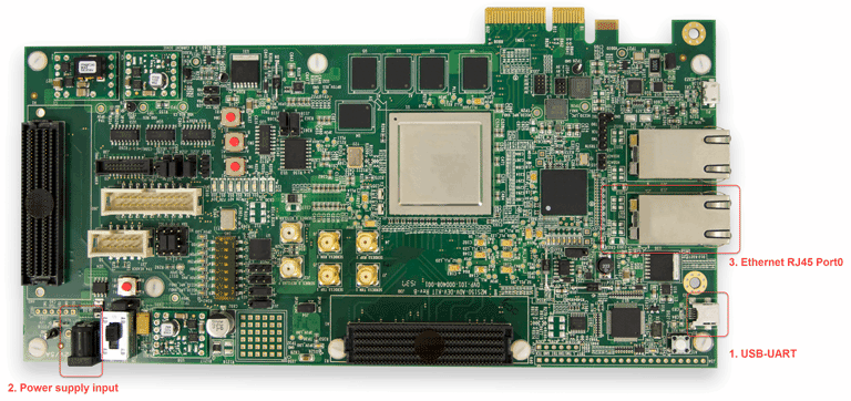
USBケーブルをボード上のUSB-UART端子に接続します。
電源ケーブルを電源入力(12V DC)に接続します。
RJ45 ケーブルを RJ45-Port0 に差し込みます。
FPGAをプログラムする
FPGA-in-the-Loop Wizard を使用して FPGA をプログラムする手順に従います。
Microchip Polarfire 評価キットのインストール
Microchip Polarfire 評価キットには特別なセットアップが必要です。適切な接続を確保するには、次の手順に従ってください。
ボード設定
機能を確保するには、ボードを接続して次のように設定します。
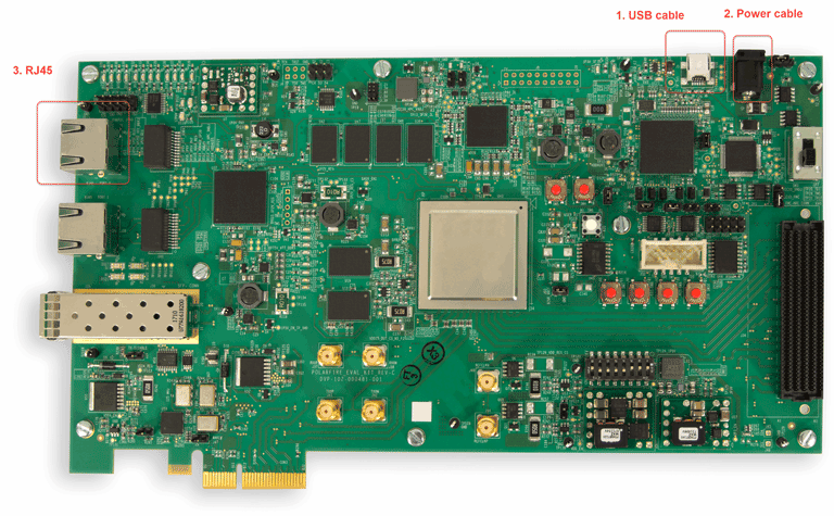
USB ケーブルをボード上の J5 コネクタに接続します。
電源ケーブルをボード上の J9 ジャック (12V DC、5A) に接続します。
RJ45 ケーブルを RJ45-Port0 (J15 コネクタ) に差し込みます。
ボード上のジャンパーを次のように設定します。
J28 – 閉鎖
J27 – 閉鎖
J227 – 閉鎖
J26 – 閉鎖
J20 – 2-3 クローズ
J21 – 2-3 クローズ
J22 – 2-3 クローズ
J18 – 2-3 クローズ
J19- 2-3 閉鎖
J23 – オープン
FPGAをプログラムする
FPGA-in-the-Loop Wizard を使用して FPGA をプログラムする手順に従います。