Deploy Applications to Target Hardware
By default, the Embedded Coder® software generates application code that does not require an external real-time executive or operating system. Generated application code requires minimal modification to be adapted to the target hardware. The architecture of the application code supports execution of models with single or multiple sample rates.
Generate Code for an Application
To generate code for an application:
Select the model configuration parameter Generate an example main program. This enables the Target operating system menu.
From the Target operating system menu, select
BareBoardExample.Generate code.
Different code is generated for multirate models depending on these factors:
Whether the model executes in single-tasking or multitasking mode.
Whether or not reusable code is being generated.
These factors can impact the scheduling algorithms used in generated code, and in some cases impact the API for the model entry-point functions. The following sections discuss these variants.
Generated Application Code
The core of generated application code is the main loop. On each iteration, the main loop executes a background or null task and checks for a termination condition.
The main loop is periodically interrupted by a timer. The function
rt_OneStep is installed as a timer interrupt service routine (ISR) or
is called from a timer ISR at each clock step.
The execution driver, rt_OneStep, sequences calls to
model_steprt_OneStep differs depending on whether the model is single-rate or
multirate. For a single-rate model, rt_OneStep simply calls the
model_steprt_OneStep prioritizes and schedules execution of blocks according
to the rates at which they run.
Main Program
Overview of Operation
This pseudocode shows the execution of a generated example main program.
main()
{
  Initialization (including installation of rt_OneStep as an
    interrupt service routine for a real-time clock)
  Initialize and start timer hardware
  Enable interrupts
  While(not Error) and (time < final time)
    Background task
  EndWhile
  Disable interrupts (Disable rt_OneStep from executing)
  Complete any background tasks
  Shutdown
}
The pseudocode is a design for a harness program to drive code generated for your model. The main program implements this design partially. You must modify it according to target environment software specifications.
Guidelines for Modifying Main Program
Make these changes in the production version of the main program module that implements your harness program:
Call
model_initializeInitialize target-specific data structures and hardware, such as ADCs or DACs.
Install
rt_OneStepas a timer ISR.Initialize timer hardware.
Enable timer interrupts and start the timer.
rtModelis not in a valid state until the main program callsmodel_initializemodel_initializeOptionally, insert background task calls in the main loop.
On termination of the main loop (if applicable):
Disable timer interrupts.
Perform target-specific cleanup such as zeroing DACs.
Detect and handle errors. Note that even if your program is designed to run indefinitely, you may need to handle severe error conditions, such as timer interrupt overruns.
You can use the macros
rtmGetErrorStatusandrtmSetErrorStatusto detect and signal errors.
rt_OneStep and Scheduling Considerations
Overview of Operation
The operation of rt_OneStep depends upon
Whether the model is single-rate or multirate. In a single-rate model, the sample times of blocks in the model and the model fixed step size are the same. A model for which the sample times and step size do not meet these conditions is a multirate model.
The model solver mode (
SingleTaskingversusMultiTasking)
Permitted Solver Modes for Embedded Real-Time System Target Files
summarizes the valid solver modes for single-rate and multirate models. For a single-rate
model, only SingleTasking solver mode is allowed.
Permitted Solver Modes for Embedded Real-Time System Target Files
| Mode | Single-Rate | Multirate |
|---|---|---|
| Allowed | Allowed |
| Disallowed | Allowed |
| Allowed (defaults to
| Allowed (defaults to
|
The generated code for rt_OneStep (and associated timing data
structures and support functions) is tailored to the number of rates in the model and to
the solver mode.
Single-Rate Single-Tasking Operation
The only valid solver mode for a single-rate model is
SingleTasking. Such models run in “single-rate”
operation.
This pseudocode shows the design of rt_OneStep in a single-rate
program.
rt_OneStep()
{
  Check for interrupt overflow or other error
  Enable "rt_OneStep" (timer) interrupt
  Model_Step()  -- Time step combines output,logging,update
}
For the single-rate case, the generated
model_step
void model_step(void)
Single-rate rt_OneStep executes
model_steprt_OneStep maintains and checks a
timer overrun flag. On entry, the main program disables timer interrupts until after
checking the overrun flag and for other error conditions. If the overrun flag is clear,
rt_OneStep sets the flag, and proceeds with timer interrupts
enabled.
The main program clears the overrun flag if
model_steprt_OneStep is reinterrupted by the
timer before completing model_steprt_OneStep signals
an error and returns immediately. You can change this behavior if you want to handle the
condition differently.
The design of rt_OneStep assumes that the main program disables
interrupts before calling rt_OneStep. The main program should not
interrupt rt_OneStep until after checking the setting of the interrupt
overflow flag.
Multirate Multitasking Operation
In a multirate multitasking system, the generated example main program uses a prioritized, preemptive multitasking scheme to execute the different sample rates in a model.
This pseudocode shows the design of rt_OneStep in a multirate
multitasking program.
rt_OneStep()
{
  Check for base-rate interrupt overrun
  Enable "rt_OneStep" interrupt
  Determine which rates need to run this time step

  Model_Step0()        -- run base-rate time step code

  For N=1:NumTasks-1   -- iterate over sub-rate tasks
    If (sub-rate task N is scheduled)
    Check for sub-rate interrupt overrun
      Model_StepN()    -- run sub-rate time step code
    EndIf
  EndFor
}
Task Identifiers. The generated main program groups the execution of blocks that use different
sample rates into different tasks. The code generator assigns each block that executes
at a given sample rate a task identifier (tid),
which associates the code for that block with a task that executes at that rate. Where
there are NumTasks tasks in the system, the range of task identifiers
is 0..NumTasks-1.
Prioritization of Base-Rate and Subrate Tasks. The scheduler prioritizes tasks in descending order by rate. The
base-rate task runs at the fastest rate in the system (the
hardware clock rate). The base-rate task has highest priority (tid
0). The next fastest task (tid 1) has the next highest priority, and
so on down to the slowest, lowest priority task (tid
NumTasks-1).
The slower tasks, running at multiples of the base rate, are subrate tasks.
Rate Grouping and Rate-Specific model_step Functions. For a single-rate model, the main program performs block output computations by
calling a single entry-point function,
model_stepmodel_stepN
model_stepN
For example, for a model named my_model that has three rates, the
code generator produces these entry-point functions:
void my_model_step0 (void);
void my_model_step1 (void);
void my_model_step2 (void);
Each
model_stepNtid
. The code generator groups block code that
executes within task NNmodel_stepN
Scheduling model_stepN Execution. On each clock tick, rt_OneStep maintains scheduling counters and
event flags for each subrate task. The code generator
implements:
Counters as
taskCounterarrays indexed ontidEvent flags as arrays indexed on
tid.
The scheduler uses rt_OneStep to maintain scheduling counters
and task flags for subrates. The scheduling counters are clock rate dividers that count
up the sample period associated with each subrate task. A pair of tasks that exchanges
data maintains an interaction flag at the faster rate. Task interaction flags indicate
that fast and slow tasks are scheduled to run.
The event flags indicate whether a given task is scheduled for execution.
rt_OneStep maintains the event flags based on a task counter that
is maintained by code in the main program for the model. When a counter indicates that
the sample period for a task has elapsed, the main code sets the event flag for that
task.
On each invocation, rt_OneStep updates its scheduling data
structures and steps the base-rate task (rt_OneStep calls
model_step0rt_OneStep iterates over the
scheduling flags in tid order, unconditionally calling
model_stepN
Preemption. The design of rt_OneStep assumes that the main program disables
interrupts before calling rt_OneStep. The main program should not
interrupt rt_OneStep until after checking the base-rate interrupt
overflow flag (see pseudocode above).
The event flag array and loop variables that rt_OneStep
uses are stored as local stack variables, making rt_OneStep
reentrant. If rt_OneStep is reinterrupted, higher priority tasks
preempt lower priority tasks. Upon return from interrupt, lower priority tasks resume in
the previously scheduled order.
Overrun Detection. Multirate rt_OneStepmaintains an array of timer overrun flags.
rt_OneStep detects timer overrun, per task, by the same logic as
single-rate rt_OneStep.
If have developed multirate S-functions, or if you use a customized static main function module, see Rate Grouping Compliance and Compatibility Issues for information about how to adapt your code for rate grouping compatibility. This adaptation produces more efficient code for multirate, multitasking models.
Multirate Single-Tasking Operation
In a multirate single-tasking program, sample times in the model must be an integer multiple of the fixed-step size configured for the model.
In a multirate single-tasking program, blocks execute at different rates, but under
the same task identifier. The operation of rt_OneStep, is a simplified
version of multirate multitasking operation. Rate grouping is not used. The only task is
the base-rate task. The code generator produces one
model_step
void model_step(void)
On each clock tick, rt_OneStep checks the overrun flag and calls
model_steprate_scheduler (rather than
rate_monotonic_scheduler). The scheduler maintains scheduling
counters on each clock tick. There is one counter for each sample rate in the model. The
counters are implemented in an array (indexed on tid) within the
Timing structure of rtModel.
The counters are clock rate dividers that count the sample period associated with each
subrate task. When a counter indicates that a sample period for a given rate has elapsed,
rate_scheduler clears the counter. This condition indicates that
blocks running at that rate should execute on the next call to
model_step
Guidelines for Modifying rt_OneStep
rt_OneStep does not require extensive modification. The only
required change is to reenable interrupts after the overrun flags and error conditions are
checked. If applicable:
Save and restore your FPU context on entry and exit to
rt_OneStep.Set model inputs associated with the base rate before calling
model_step0Get model outputs associated with the base rate after calling
model_step0rt_OneStepto read a value from a continuous output port after each base-rate model step, see the relevant cautionary guideline below.In a multirate, multitasking model, set model inputs associated with subrates before calling
model_stepNIn a multirate, multitasking model, get model outputs associated with subrates after calling
model_stepN
Comments in rt_OneStep indicate the place to add your code.
In multirate rt_OneStep, you can optimize the generated code by
unrolling for and while loops.
In addition, you can modify the overrun behavior to continue execution after error recovery is complete.
Observe these guidelines:
You should not modify the way in which the counters, event flags, or other timing data structures are set in
rt_OneStep, or in functions called fromrt_OneStep. Thert_OneSteptiming data structures (includingrtModel) and logic are critical to the operation of the generated program.If you customize the main program module to read model outputs after each base-rate model step and select model configuration parameters Support: continuous time and Single output/update function can cause output values read from
mainfor a continuous output port to differ from the corresponding output values in data logged for the model. While logged data is a snapshot of output at major time steps, output read frommainafter the base-rate model step function executes reflects intervening minor time steps. To eliminate the discrepancy, separate the generated output and update functions (clear model configuration parameter Single output/update function) or place a Zero-Order Hold block before the continuous output port.You might observe a mismatch between results from simulation and logged MAT file results from generated code if you do not set model inputs before each time you call the model step function. In the generated example main program, the following comments show the locations for setting the inputs and stepping the model with your code:
/* Set model inputs here */
/* Step the model */
If your model applies signal reuse and you are using
MatFileLoggingfor comparing results from simulation against generated code, modifyrt_OneStepto write model inputs in every time step as directed by these comments. Alternatively, you use a SIL or PIL approach for verification (see Choose a SIL or PIL Approach).
Static Main Function Module
Overview
A strategy for deploying generated application code is to use model configuration
parameter Generate an example main program option to
generate an example main program module (ert_main.c or
.cpp). For more information, see Generate Code for an Application.
Alternatively, you can clear the Generate an example main program parameter and use a generated static main function module as an example or template for developing your embedded application. Static main function modules provided by MathWorks® include:
matlabroot/rtw/c/src/common/rt_main.cNonreusable functionsetting for model configuration parameter Code interface packaging.matlabroot/rtw/c/src/common/rt_malloc_main.cReusable functionsetting for parameter Code interface packaging. Select model configuration parameter Use dynamic memory allocation for model initialization and set parameter Pass root-level I/O as toPart of model data structure.matlabroot/rtw/c/src/common/rt_cppclass_main.cppC++ classsetting for parameter Code interface packaging.
Static main functions are not part of the generated code. The programs are provided as a basis for developing custom modifications and for use in simulation.
A static main function contains:
rt_OneStep—A timer interrupt service routine (ISR) that calls the entry-point functionmodel_stepSkeletal
mainfunction—As provided,mainis useful for simulation only. You must modifymainfor real-time interrupt-driven execution.
For single-rate models, operation of rt_OneStep and the
main function in the static main function are the same as they are
in the automatically generated version described in Deploy Applications to Target Hardware. For multirate,
multitasking models, the static main function and generated code differ as described in
the next section.
To develop an application by using a static main function:
Copy the program module to your working folder.
Rename the file. For example, rename
rt_main.ctomodel_rt_main.cCustomize the program module content.
If you are using a template makefile build approach, modify the template makefile settings such that the build process creates a corresponding object file in the build folder. For example, depending on the target platform,
model_rt_main.objmodel_rt_main.oIf you are using a makefile-based toolchain approach:
Use the
setTargetProvidesMainfunction to disable the inclusion of the shipped staticmainfunction in the build process.Use the
addSourceFilesfunction to add the source file for yourmainprogram.
If your existing application depends upon a static ert_main.c
developed in releases before R2012b, rt_main.c,
rt_malloc_main.c, or rt_cppclass_main.cpp, you
might need to continue using that static main function.
Rate Grouping and Static Main Function
ERT-based system target files can use a static main function module and disallow use of the model configuration parameter Generate an example main program. A custom system target file does not disallow use of that model configuration parameter when target-specific changes have been made to the static main function and those modifications must be preserved. A generated example main program does not preserve the changes to the static main function.
For models configured for multitasking (Treat each discrete rate
as a separate task is selected) or concurrency (Allow
task to execute concurrently on target is selected), the code generator uses
a rate grouping scheme, producing a step entry-point function for each rate
(model_stepNN
To specify that only the rate-based step functions are generated without the wrapper
function, use the TLC variable RateBasedStepFcn. If your target calls
the rate grouping compatible function directly, set RateBasedStepFcn to
1. In this case, the wrapper function is not generated.
In your system target file, prior to the %include
"codegenentry.tlc" statement, set the TLC variable
RateBasedStepFcn to 1. Alternatively, set
RateBasedStepFcn to 1 in your
target_settings.tlc file.
Modify the Static Main Function
Make few modifications to the main loop and the rt_OneStep
function. See Guidelines for Modifying Main Program and Guidelines for Modifying rt_OneStep.
Replace the rt_OneStep call in the main loop with a background task
call or null statement.
Other modifications you might need to make are:
If applicable, follow comments in the code regarding where to add code for reading and writing model I/O and saving and restoring FPU context.
If you modify
rt_main.c,rt_malloc_main.c, orrt_cppclass_main.cppto read a value from a continuous output port after each base-rate model step, see the relevant guideline in Guidelines for Modifying rt_OneStep.When you clear the model configuration parameter Generate an example main program, the code generator produces
rtmodel.hto provide an interface between the main program module and generated model code. If you create your own static main function module, includertmodel.h.Alternatively, you can suppress generation of
rtmodel.hand includemodel.hrtmodel.h, add this statement to your system target file:%assign AutoBuildProcedure = 0
If you cleared model configuration parameter Terminate function required, remove or comment out these items in your production version of
rt_main.c,rt_malloc_main.c, orrt_cppclass_main.cpp:The
#if TERMFCN...compile-time error checkThe call to
MODEL_TERMINATE
For only
rt_main.c: If you do not want to combine output and update functions, clear model configuration parameter Single output/update function and make these changes in your production version ofrt_main.c:Replace calls to
MODEL_STEPwith calls toMODEL_OUTPUTandMODEL_UPDATE.Remove the
#if ONESTEPFCN...error check.
The static program module
rt_main.cdoes not supportReusable functioncode interface packaging. If you try to use it, a compile-time error occurs.#if MULTI_INSTANCE_CODE==1
Modify Static Main to Allocate and Access Model Instance Data
If you are using a static main function module and your model is configured for
Reusable function code interface packaging, but the model
configuration parameter Use dynamic memory allocation for model
initialization is cleared, allocate model instance data statically or
dynamically by the calling main code. Pointers to the individual model data structures,
such as Block IO, DWork, and Parameters, must be set up in the top-level real-time model
data structure.
To support main modifications, the build process generates a subset of these real-time
model (RTM) macros, based on the data requirements of your model, into
model.h
| RTM Macro Syntax | Description |
|---|---|
rtmGetBlockIO(rtm) | Get the block I/O data structure |
rtmSetBlockIO(rtm,val) | Set the block I/O data structure |
rtmGetContStates(rtm) | Get the continuous states data structure |
rtmSetContStates(rtm,val) | Set the continuous states data structure |
rtmGetDefaultParam(rtm) | Get the default parameters data structure |
rtmSetDefaultParam(rtm,val) | Set the default parameters data structure |
rtmGetPrevZCSigState(rtm) | Get the previous zero-crossing signal state data structure |
rtmSetPrevZCSigState(rtm,val) | Set the previous zero-crossing signal state data structure |
rtmGetRootDWork(rtm) | Get the DWork data structure |
rtmSetRootDWork(rtm,val) | Set the DWork data structure |
rtmGetU(rtm) | Get the root inputs data structure (when root inputs are passed as part of the model data structure) |
rtmSetU(rtm,val) | Set the root inputs data structure (when root inputs are passed as part of the model data structure) |
rtmGetY(rtm) | Get the root outputs data structure (when root outputs are passed as part of the model data structure) |
rtmSetY(rtm,val) | Set the root outputs data structure (when root outputs are passed as part of the model data structure) |
To access individual model data structures within the RTM data structure, use these
macros in your static main function. For example, consider the example model
Reusable.
openExample('ecoder/ReusableCodeInterfaceExample', 'supportingFile', 'Reusable');
Suppose the model is configured with Reusable function code
interface packaging, Use dynamic memory allocation for model
initialization cleared, Pass root-level I/O as set to
Individual arguments, and Optimization
pane option Remove root level I/O zero initialization is cleared.
Building the model generates these model data structures and model entry-points into
Reusable.h:
/* Block states (auto storage) for system '<Root>' */
typedef struct {
  real_T Delay_DSTATE;                 /* '<Root>/Delay' */
} D_Work;

/* Parameters (auto storage) */
struct Parameters_ {
  real_T k1;                           /* Variable: k1
                                        * Referenced by: '<Root>/Gain'
                                        */
};

/* Model entry point functions */
extern void Reusable_initialize(RT_MODEL *const rtM, real_T *rtU_In1,
  real_T *rtU_In2, real_T *rtY_Out1);
extern void Reusable_step(RT_MODEL *const rtM, real_T rtU_In1, real_T
  rtU_In2, real_T *rtY_Out1);
If you do not select the model configuration parameter Generate an example
main program for the model, Reusable.h contains
definitions for the RTM macros rtmGetDefaultParam,
rtmsetDefaultParam, rtmGetRootDWork, and
rtmSetRootDWork.
For reference, the generated rtmodel.h file contains an example
parameter definition that has initial values (nonexecuting code):
#if 0

/* Example parameter data definition with initial values */
static Parameters rtP = {
  2.0                                  /* Variable: k1
                                        * Referenced by: '<Root>/Gain'
                                        */
};                                     /* Modifiable parameters */

#endif
In the definitions section of your static main file, you can use this code to
statically allocate the real-time model data structures and arguments for the
Reusable model:
static RT_MODEL rtM_;
static RT_MODEL *const rtM = &rtM_;    /* Real-time model */
static Parameters rtP = {
  2.0                                  /* Variable: k1
                                        * Referenced by: '<Root>/Gain'
                                        */
};                                     /* Modifiable parameters */

static D_Work rtDWork;                 /* Observable states */

/* '<Root>/In1' */
static real_T rtU_In1;

/* '<Root>/In2' */
static real_T rtU_In2;

/* '<Root>/Out1' */
static real_T rtY_Out1;
In the body of your main function, you can use these RTM macro calls to set up the model parameters and DWork data in the real-time model data structure:
int_T main(int_T argc, const char *argv[])
{
...
/* Pack model data into RTM */

rtmSetDefaultParam(rtM, &rtP);
rtmSetRootDWork(rtM, &rtDWork);

/* Initialize model */
Reusable_initialize(rtM, &rtU_In1, &rtU_In2, &rtY_Out1);
...
}
Follow a similar approach to set up multiple instances of model data, where the
real-time model data structure for each instance has its own data. You must initialize the
parameter structure (rtP) for each instance, to the values that you
want, statically as part of the rtP data definition or at run
time.
Rate Grouping Compliance and Compatibility Issues
Main Program Compatibility
When you clear model configuration parameter Generate an example
main program, the code generator produces slightly different rate grouping
code, for compatibility with the older static ert_main.c module. See
Rate Grouping and Static Main Function for details.
Make Your S-Functions Rate Grouping Compliant
Built-in Simulink® blocks and DSP System Toolbox™ blocks are compliant with the requirements for generating rate grouping code. However, user-written multirate inlined S-functions might not be rate grouping compliant. Noncompliant blocks generate less efficient code, but are otherwise compatible with rate grouping. To take full advantage of the efficiency of rate grouping, upgrade multirate inlined S-functions to be fully rate grouping compliant. You should upgrade your TLC S-function implementations, as described in this section.
Use of noncompliant multirate blocks to generate rate-grouping code generates dead code. This can cause two problems:
Reduced code efficiency.
Warning messages issued at compile time. Such warnings are caused when dead code references temporary variables before initialization. Since the dead code does not run there is no impact to ,the run-time behavior of the generated code.
To make your S-functions rate grouping compliant, use these TLC functions to generate
ModelOutputs and ModelUpdate code,
respectively:
OutputsForTID(block, system, tid)
UpdateForTID(block, system, tid)
These code listings illustrate generation of output computations without rate grouping (Listing 1) and with rate grouping (Listing 2).
The
tidargument is a task identifier (0..NumTasks-1).Only code guarded by the
tidpassed intoOutputsForTIDis generated. Theif (%<LibIsSFcnSampleHit(portName)>)test is not used inOutputsForTID.When generating rate grouping code,
OutputsForTIDand/orUpdateForTIDis called during code generation. When generating non-rate-grouping code,Outputsand/orUpdateis called.In rate grouping compliant code, the top-level
Outputsand/orUpdatefunctions callOutputsForTIDand/orUpdateForTIDfunctions for each rate (tid) involved in the block. The code returned byOutputsForTIDandUpdateForTIDmust be guarded by the correspondingtidguard as in lListing 2:if (%<LibIsSFcnSampleHit(portName)>)
Listing 1: Outputs Code Generation Without Rate Grouping
%% multirate_blk.tlc
%implements "multirate_blk" "C"
%% Function: mdlOutputs =====================================================
%% Abstract:
%%
%% Compute the two outputs (input signal decimated by the
%% specified parameter). The decimation is handled by sample times.
%% The decimation is only performed if the block is enabled.
%% Each port has a different rate.
%%
%% Note, the usage of the enable should really be protected such that
%% each task has its own enable state. In this example, the enable
%% occurs immediately which may or may not be the expected behavior.
%%
%function Outputs(block, system) Output
/* %<Type> Block: %<Name> */
%assign enable = LibBlockInputSignal(0, "", "", 0)
{
int_T *enabled = &%<LibBlockIWork(0, "", "", 0)>;
%if LibGetSFcnTIDType("InputPortIdx0") == "continuous"
%% Only check the enable signal on a major time step.
if (%<LibIsMajorTimeStep()> && ...
%<LibIsSFcnSampleHit("InputPortIdx0")>) {
*enabled = (%<enable> > 0.0);
}
%else
if (%<LibIsSFcnSampleHit("InputPortIdx0")>) {
*enabled = (%<enable> > 0.0);
}
%endif
if (*enabled) {
%assign signal = LibBlockInputSignal(1, "", "", 0)
if (%<LibIsSFcnSampleHit("OutputPortIdx0")>) {
%assign y = LibBlockOutputSignal(0, "", "", 0)
%<y> = %<signal>;
}
if (%<LibIsSFcnSampleHit("OutputPortIdx1")>) {
%assign y = LibBlockOutputSignal(1, "", "", 0)
%<y> = %<signal>;
}
}
}
%endfunction
%% [EOF] sfun_multirate.tlcListing 2: Outputs Code Generation With Rate Grouping
%% example_multirateblk.tlc
%implements "example_multirateblk" "C"
%% Function: mdlOutputs =====================================================
%% Abstract:
%%
%% Compute the two outputs (the input signal decimated by the
%% specified parameter). The decimation is handled by sample times.
%% The decimation is only performed if the block is enabled.
%% All ports have different sample rate.
%%
%% Note: the usage of the enable should really be protected such that
%% each task has its own enable state. In this example, the enable
%% occurs immediately which may or may not be the expected behavior.
%%
%function Outputs(block, system) Output
%assign portIdxName = ["InputPortIdx0","OutputPortIdx0","OutputPortIdx1"]
%assign portTID = [%<LibGetGlobalTIDFromLocalSFcnTID("InputPortIdx0")>, ...
%<LibGetGlobalTIDFromLocalSFcnTID("OutputPortIdx0")>, ...
%<LibGetGlobalTIDFromLocalSFcnTID("OutputPortIdx1")>]
%foreach i = 3
%assign portName = portIdxName[i]
%assign tid = portTID[i]
if (%<LibIsSFcnSampleHit(portName)>) {
%<OutputsForTID(block,system,tid)>
}
%endforeach
%endfunction
%function OutputsForTID(block, system, tid) Output
/* %<Type> Block: %<Name> */
%assign enable = LibBlockInputSignal(0, "", "", 0)
%assign enabled = LibBlockIWork(0, "", "", 0)
%assign signal = LibBlockInputSignal(1, "", "", 0)
%switch(tid)
%case LibGetGlobalTIDFromLocalSFcnTID("InputPortIdx0")
%if LibGetSFcnTIDType("InputPortIdx0") == "continuous"
%% Only check the enable signal on a major time step.
if (%<LibIsMajorTimeStep()>) {
%<enabled> = (%<enable> > 0.0);
}
%else
%<enabled> = (%<enable> > 0.0);
%endif
%break
%case LibGetGlobalTIDFromLocalSFcnTID("OutputPortIdx0")
if (%<enabled>) {
%assign y = LibBlockOutputSignal(0, "", "", 0)
%<y> = %<signal>;
}
%break
%case LibGetGlobalTIDFromLocalSFcnTID("OutputPortIdx1")
if (%<enabled>) {
%assign y = LibBlockOutputSignal(1, "", "", 0)
%<y> = %<signal>;
}
%break
%default
%% error it out
%endswitch
%endfunction
%% [EOF] sfun_multirate.tlc Generate Code That Dereferences Data from a Literal Memory Address
This example shows how to generate code that reads the value of a signal by dereferencing a memory address that you specify. With this technique, you can generate a control algorithm that interacts with memory that your hardware populates (for example, memory that stores the output of an analog-to-digital converter in a microcontroller).
In this example, you generate an algorithm that acquires input data from a 16-bit block of memory at address 0x8675309. Assume that a hardware device asynchronously populates only the lower 10 bits of the address. The algorithm must treat the address as read-only (const), volatile (volatile) data, and ignore the upper 6 bits of the address.
The generated code can access the data by defining a macro that dereferences 0x8675309 and masks the unnecessary bits:
#define A2D_INPUT ((*(volatile const uint16_T *)0x8675309)&0x03FF)
To configure a model to generate code that defines and uses this macro:
Create the example model.
Create package to contain definitions of data class and storage class.
Use Custom Storage Class Designer to create a storage class.
Define a class to store property settings for the storage class.
Write Target Language Compiler (TLC) code that emits the correct C code for the storage class.
Define a class for the inport data.
Load the package into the Embedded Coder® Dictionary.
Configure the model root-level inport to use the storage class.
Generate and inspect the code.
For an example that shows how to use the Custom Storage Class Designer without writing TLC code, see Create and Apply Storage Class Defined in User-Defined Package.
As an alternative to writing TLC code, you can use memory sections to generate code that includes pragmas. Depending on your build toolchain, you can use pragmas to specify a literal memory address for storing a global variable. For more information about memory sections, see Control Data and Function Placement in Memory by Inserting Pragmas.
Derivation of Macro Syntax
In this example, you configure the generated code to define and use the dereferencing macro. To determine the correct syntax for the macro, start by recording the target address.
0x8675309
Cast the address as a pointer to a 16-bit integer. Use the Simulink® Coder™ data type name uint16_T.
(uint16_T *)0x8675309
Add the storage type qualifier const because the generated code must not write to the address. Add volatile because the hardware can populate the address at an arbitrary time.
(volatile const uint16_T *)0x8675309
Dereference the address.
*(volatile const uint16_T *)0x8675309
After the dereference operation, apply a mask to retain only the 10 bits that the hardware populates. Use explicit parentheses to control the order of operations.
(*(volatile const uint16_T *)0x8675309)&0x03FF
As a safe coding practice, wrap the entire construct in another layer of parentheses.
((*(volatile const uint16_T *)0x8675309)&0x03FF)
Create Example Model
Create the example model ex_memmap_simple.
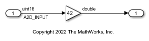
For the Inport block, set the output data type to uint16. Name the signal as A2D_INPUT. The Inport block and the signal line represent the data that the hardware populates.
For the Gain block, set the output data type to double.
Create Package to Contain Definitions of Data Class and Storage Class
In your current folder, create MATLAB® namespace folder +MemoryMap. The folder contains files that define a package named MemoryMap.
To make the package available for use outside of your current folder, you can add the folder that contains the namespace folder +MemoryMap to the MATLAB® search path.
Create Storage Class
To generate code that defines and reads A2D_INPUT as a macro, you must create a storage class that you can apply to the model root-level inport. Later, you write TLC code that complements the storage class.
Open the Custom Storage Class designer in advanced mode. To design a storage class that operates through custom TLC code, you must use the advanced mode.
cscdesigner('MemoryMap','-advanced');
In the Custom Storage Class Designer, click New. A new custom storage class, NewCSC_1, appears in the list of storage class definitions.
Rename the storage class to MemoryMappedAddress.
For MemoryMappedAddress, on the General tab, set:
Type to
Other. The storage class can operate through custom TLC code that you write later.Data scope to
Exported. For data items that use this custom storage class, Simulink Coder generates the definition (for example, the#definestatement that defines a macro).Data initialization to
None. Simulink Coder does not generate code that initializes the data item. Use this setting because this custom storage class represents read-only data. You do not selectMacrobecause the Custom Storage Class Designer does not allow you to useMacrofor signal data.Definition file to
Specify(leave the text box empty). For data items that consume memory in the generated code, Definition file specifies the.csource file that allocates the memory. This storage class yields a macro, which does not require memory. Typically, header files (.h), not.cfiles, define macros. Setting Definition file toSpecifyinstead ofInstance specificprevents users of the storage class from unnecessarily specifying a definition file.Header file to
Instance specific. To control the file placement of the macro definition, the user of the storage class must specify a header file for each data item that uses this storage class.Owner to
Specify(leave the text box empty). Owner applies only to data items that consume memory.
After you finish selecting the settings, click Apply and Save.
Now, when you apply the storage class to a data item, such as inport In1, you can specify a header file to contain the generated macro definition. You cannot yet specify a memory address for the data item. To enable specification of a memory address, create a custom attributes class that you can associate with the MemoryMappedAddress storage class.
Define Class to Store Property Settings for Storage Class
Define a MATLAB class to store additional information for data items that use the storage class. In this case, the additional information is the memory address.
In the namespace folder +MemoryMap, create a folder named @MemoryMapAttribs.
In the @MemoryMapAttribs folder, create a file named MemoryMapAttribs. The file defines a class that derives from the built-in class Simulink.CustomStorageClassAttributes.
classdef MemoryMapAttribs < Simulink.CustomStorageClassAttributes
    properties( PropertyType = 'char' )
        MemoryAddress = '';
    end
end
Later, you associate this MATLAB class with the MemoryMappedAddress storage class. Then, when you apply the storage class to a data item, you can specify a memory address.
Write TLC Code That Emits Correct C Code
Write TLC code that uses the attributes of the storage class, such as HeaderFile and MemoryAddress, to generate correct C code for each data item.
In the namespace folder +MemoryMap, create a folder named tlc.
Navigate to the new folder.
Inspect the built-in template TLC file, TEMPLATE_v1.tlc.
edit(fullfile(matlabroot,...
    'toolbox','rtw','targets','ecoder','csc_templates','TEMPLATE_v1.tlc'))
Save a copy of TEMPLATE_v1.tlc in the tlc folder. Rename the copy memory_map_csc.tlc.
In memory_map_csc.tlc, find the portion that controls the generation of C-code data declarations.
    %case "declare"

      %% LibDefaultCustomStorageDeclare is the default declare function to
      %% declares a global variable whose identifier is the name of the data.
      %return "extern %<LibDefaultCustomStorageDeclare(record)>"
      %%break

    %% ==========================================================================
The declare case (%case) constructs a return value (%return), which the code generator emits into the header file that you specify for each data item. To control the C code that declares each data item, adjust the return value in the declare case.
Replace the existing %case content with this code, which specifies a different return value:
%case "declare"

        %% In TLC code, a 'record' is a data item (for example, a signal line).
        %% 'LibGetRecordIdentifier' returns the name of the data item.
        %assign id = LibGetRecordIdentifier(record)

        %assign dt = LibGetRecordCompositeDataTypeName(record)

        %% The 'CoderInfo' property of a data item stores a
        %% 'Simulink.CoderInfo' object, which stores code generation settings
        %% such as the storage class or custom storage class that you specify
        %% for the item.
        %assign ci = record.Object.ObjectProperties.CoderInfo
        %% The 'ci' variable now stores the 'Simulink.CoderInfo' object.

        %% By default, the 'CustomAttributes' property of a 'Simulink.CoderInfo'
        %% object stores a 'Simulink.CustomStorageClassAttributes' object.
        %% This nested object stores specialized code generation settings
        %% such as the header file and definition file that you specify for
        %% the data item.
        %%
        %% The 'MemoryMap' package derives a new class,
        %% 'MemoryMapAttribs', from 'Simulink.CustomStorageClassAttributes'.
        %% The new class adds a property named 'MemoryAddress'.
        %% This TLC code determines the memory address of the data item by
        %% acquiring the value of the 'MemoryAddress' property.
        %assign ca = ci.Object.ObjectProperties.CustomAttributes
        %assign address = ca.Object.ObjectProperties.MemoryAddress

        %assign width = LibGetDataWidth(record)

        %% This TLC code constructs the full macro, with correct C syntax,
        %% based on the values of TLC variables such as 'address' and 'dt'.
        %% This TLC code also asserts that the data item must be a scalar.
        %if width == 1
                %assign macro = ...
                    "#define %<id> ((*(volatile const %<dt>*)%<address>) & 0x03FF)"
        %else
                %error( "Non scalars are not supported yet." )
        %endif

        %return "%<macro>"
      %%break

    %% ==========================================================================
The new TLC code uses built-in, documented TLC functions, such as LibGetRecordIdentifier, and other TLC commands and operations to access information about the data item. Temporary variables such as dt and address store that information. The TLC code constructs the full macro, with the correct C syntax, by expanding the variables, and stores the macro in the variable macro.
In the same file, find the portion that controls the generation of data definitions.
    %case "define"

      %% LibDefaultCustomStorageDefine is the default define function to define
      %% a global variable whose identifier is the name of the data.  If the
      %% data is a parameter, the definition is also statically initialized to
      %% its nominal value (as set in MATLAB).
      %return "%<LibDefaultCustomStorageDefine(record)>"
      %%break

    %% ==========================================================================
The define case derives a return value that the code generator emits into a .c file, which defines data items that consume memory.
Replace the existing %case content with this new content:
    %case "define"
      %return ""
      %%break

    %% ==========================================================================
MemoryMappedAddress yields a macro in the generated code, so you use the declare case instead of the define case to construct and emit the macro. To prevent the define case from emitting a duplicate macro definition, the new TLC code returns an empty string.
Find the portion that controls the generation of code that initializes data.
    %case "initialize"

      %% LibDefaultCustomStorageInitialize is the default initialization
      %% function that initializes a scalar element of a global variable to 0.
      %return LibDefaultCustomStorageInitialize(record, idx, reim)
      %%break

    %% ==========================================================================
The initialize case generates code that initializes data items (for example, in the model_initialize function).
Replace the existing %case content with this new content:
    %case "initialize"
      %return ""
      %%break

    %% ==========================================================================
MemoryMappedAddress yields a macro, so the generated code must not attempt to initialize the value of the macro. The new TLC code returns an empty string.
Complete the Definition of the Storage Class
Your MATLAB class, MemoryMapAttribs, can enable users of your storage class, MemoryMappedAddress, to specify a memory address for each data item. To allow this specification, associate MemoryMapAttribs with MemoryMappedAddress. To generate correct C code based on the information that you specify for each data item, associate the customized TLC file, memory_map_csc.tlc, with MemoryMappedAddress.
Navigate to the folder that contains the namespace folder +MemoryMap.
Open the Custom Storage Class Designer again.
cscdesigner('MemoryMap','-advanced');
For MemoryMappedAddress, on the Other Attributes tab, set:
TLC file name to
memory_map_csc.tlc.CSC attributes class to
MemoryMap.MemoryMapAttribs.
Click Apply and Save.
Define Signal Data Class
To apply the storage class to a data element in a model, in the package namespace folder +MemoryMap, you must create a MATLAB class that derives from Simulink.Signal. When you configure the signal in the model, you select this new data class instead of the default class, Simulink.Signal.
In the package namespace folder +MemoryMap, create a folder named @Signal.
In the @Signal folder, create a file named Signal.m.
classdef Signal < Simulink.Signal
    methods
        function setupCoderInfo( this )
            useLocalCustomStorageClasses( this, 'MemoryMap' );
            return;
        end
    end
end
The file defines a class named MemoryMap.Signal. The class definition overrides the setupCoderInfo method, which the Simulink.Signal class already implements. The new implementation specifies that objects of the MemoryMap.Signal class use custom storage classes from the MemoryMap package (instead of storage classes from the Simulink package). When you configure a signal in a model by selecting the MemoryMap.Signal class, you can select the new custom storage class, MemoryMappedAddress.
Load Package into Embedded Coder Dictionary
Open the example model.
Open the Embedded Coder app.
Open the Embedded Coder Dictionary. On the C Code tab, select Code Interface > Embedded Coder Dictionary.
In the Embedded Coder Dictionary, click Manage Packages.
In the Manage Package dialog box, click Refresh. When the refresh is complete, select the package MemoryMap. Click Load.
Close the Embedded Coder Dictionary.
Configure Root-Level Inport to Use Storage Class
In the Embedded Coder app, use the Code Mappings editor and Property Inspector to configure Inport In1 to use the storage class that you defined.
Open the Code Mappings editor. On the C Code tab, select Code Interface > Individual Element Code Mappings.
In the Code Mappings Editor, on the Inports tab, select inport In1. Set the storage class for In1 to MemoryMappedAddress.
In the Property Inspector, under Code, set the HeaderFile property to memory_mapped_addresses.h and the MemoryAddress property to 0x8675309.
Save the model.
Generate and Inspect Code
Generate code from the model.
### Searching for referenced models in model 'ex_memmap_simple'.
### Total of 1 models to build.
### Starting build procedure for: ex_memmap_simple
### Successful completion of build procedure for: ex_memmap_simple

Build Summary

Top model targets:

Model             Build Reason                                         Status                        Build Duration
===================================================================================================================
ex_memmap_simple  Information cache folder or artifacts were missing.  Code generated and compiled.  0h 0m 15.075s

1 of 1 models built (0 models already up to date)
Build duration: 0h 0m 16.18s
Inspect the generated header file memory_mapped_addresses.h. The file defines the macro A2D_INPUT, which corresponds to the signal line in the model.
/* Declaration of data with custom storage class MemoryMappedAddress */
#define A2D_INPUT                      ((*(volatile const uint16_T*)0x8675309) & 0x03FF)
Inspect the generated file ex_memmap_simple.c. The generated algorithmic code (which corresponds to the Gain block) calculates the model output, rtY.Out1, by operating on A2D_INPUT.
/* Model step function */
void step(void)
{
  /* Outport: '<Root>/Out1' incorporates:
   *  Gain: '<Root>/Gain'
   *  Inport: '<Root>/In1'
   */
  rtY.Out1 = 42.0 * (real_T)A2D_INPUT;
}