Multicore Simulation and Code Generation of Dataflow Domains
Simulation of Dataflow Domains
Simulation of dataflow domains leverages the multicore CPU architecture of the host computer. It automatically partitions your model and simulates the system using multiple threads.
The first time you simulate a dataflow domain, the simulation is single threaded. During this simulation, the software performs a cost-analysis. The next time the model compiles, the software automatically partitions the system for multithreaded execution. Subsequent simulations are multithreaded.
Code Generation of Dataflow Domains
Dataflow domains support code generation for both single-core and multi-core targets. When all blocks inside a dataflow subsystem support multithreading, and the model is configured for multicore code generation, the generated code is multithreaded. During code generation, the dataflow system is automatically partitioned according to the specified target hardware.
Types of Parallelism
In both simulation and code generation of models with dataflow domains, the software identifies possible concurrencies in your system, and partitions the dataflow domain using the following types of parallelism.
Task Parallelism
Task parallelism achieves parallelism by splitting up an application into multiple tasks. Task parallelism involves distributing tasks within an application across multiple processing nodes. Some tasks can have data dependency on others, so all tasks do not run at exactly the same time.
Consider a system that involves four functions. Functions F2a() and F2b() are in parallel, that is, they can run simultaneously. In task parallelism, you can divide your computation into two tasks. Function F2b() runs on a separate processing node after it gets data Out1 from Task 1, and it outputs back to F3() in Task 1.
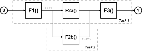
The figure shows the timing diagram for this parallelism. Task 2 does not run until it gets data Out1 from Task 1. Hence, these tasks do not run completely in parallel. The time taken per processor cycle, known as cycle time, is
t = tF1 + max(tF2a, tF2b) + tF3.

Model Pipeline Execution (Pipelining)
The software uses model pipeline execution, or pipelining, to work around the problem of task parallelism where threads do not run completely in parallel. This approach involves modifying the system to introduce delays between tasks where there is a data dependency.
In this figure, the system is divided into three tasks to run on three different processing nodes, with delays introduced between functions. At each time step, each task takes in the value from the previous time step by way of the delay.

Each task can start processing at the same time, as this timing diagram shows. These tasks are truly parallel and they are no longer serially dependent on each other in one processor cycle. The cycle time does not have any additions but is the maximum processing time of all the tasks.
t = max(Task1, Task2, Task3) = max(tF1, tF2a, tF2b, tF3).

Pipelining can be used when you can introduce delays artificially in your concurrently executing system. The resulting overhead due to this introduction must not exceed the time saved by pipelining.
Unfolding
When the cost analysis identifies a single block in a system that is computationally dominant, the system uses unfolding technology. Unfolding is a technique to improve throughput through parallelization. The software duplicates the functionality of the computationally intensive block, divides the input data into multiple pieces, and the processor performs the same operation on each piece of data.
Unfolding is used in scenarios where it is possible to process each piece of input data independently without affecting the output, and the block is stateless or contains a finite number of states.
Improve Simulation Throughput with Multicore Simulation
This example shows how to improve simulation throughput of a system by simulating a subsystem with multiple threads. To enable automatic partitioning of a system and multithreaded simulation, set the Domain of the subsystem to Dataflow. For more information on dataflow domains, see Dataflow Domain.
To begin, open
ex_staple_counting.Simulate the model and observe the frame rate of the system in the Frame Rate Display block. This number indicates the number of frames per second that Simulink® is able to process in a standard simulation.
To enable multithreaded simulation and improve the simulation throughput, set the domain of the subsystem to dataflow. If the Property Inspector is not visible, in the Modeling tab, under Design, select Property Inspector. With the subsystem selected, in the Execution tab of the Property Inspector, select Set execution domain. Set the Domain to
Dataflow.Sometimes, you can increase the available concurrency in your system by adding Latency to the system. To select an optimal latency value, use the Dataflow Simulation Assistant. Click the Dataflow assistant button to open the Dataflow Simulation Assistant.
In addition to suggesting a latency value, the Dataflow Simulation Assistant also suggests model settings for optimal simulation performance. In this example, to improve the simulation performance, the Dataflow Simulation Assistant suggests disabling the Break on Ctrl+C (Simulink) parameter. To accept the proposed model settings, next to Suggested model settings for simulation performance, click Accept all.
Next, click the Analyze button. The Dataflow Simulation Assistant analyzes the subsystem for simulation performance and suggests an optimal latency for your Dataflow Subsystem. The dataflow analysis is a two-step process. During the first step, the dataflow subsystem simulates using a single-thread. During this simulation, the software performs a cost analysis. The next time the model compiles, the software automatically partitions the subsystem into one or more threads to take advantage of concurrency in the model. Subsequent simulations are multithreaded. The assistant suggests a latency value that optimizes the throughput of the system.
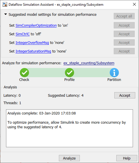
Click the Accept button to apply the suggested latency to the system. The Dataflow Simulation Assistant applies the latency to the model and indicates the number of threads the model will use during subsequent simulations. The latency of the system is indicated with a delay icon on the model canvas at the output of the subsystem.

Simulate the model again. Observe the improved simulation throughput from the multithreaded simulation in the Frame Rate Display block.
Generate Multicore Code from a Dataflow System
Configure Your Model for Multicore Code Generation
Code generation requires a Simulink® Coder™ or an Embedded Coder® license. Single-core and multicore targets are supported.
Code generated for single-core targets generates nonvirtual subsystem code.
To generate multicore code, you must configure your model for concurrent execution. If you do not configure your model for concurrent execution, the generated code will be single threaded.
In Configuration Parameters > Solver > Solver selection, choose
Fixed-stepfor the Type andauto (Automatic solver selection)for the Solver.Select the Allow tasks to execute concurrently on target check box in the Solver pane under Solver details. Selecting this check box is optional for models referenced in the model hierarchy. When you select this option for a referenced model, Simulink allows each rate in the referenced model to execute as an independent concurrent task on the target processor.
In Configuration Parameters > Code Generation > Interface > Advanced parameters, clear the MAT-file logging check box.
Click Apply to apply the settings to the model.
Generate Multicore Code
To generate multicore code, the software performs cost analysis and partitions the dataflow domain based on your specified target. The partitioning of the dataflow domain may or may not match the partitioning during simulation.
The generated C code contains one void(void) function for each
task or thread created by the dataflow system. Each of these functions consists of:
The C code corresponding to the blocks that were partitioned into that thread
The code that is generated to handle how data is transferred between the threads.
This can be in the form of pipeline delays or target-specific implementation of data synchronization semaphores.
The following multicore targets are supported for code generation.
Linux®, Windows®, and macOS desktop targets using
ert.tlcandgrt.tlc.Simulink Real-Time™ using any target file supported by Simulink Real-Time.
Embedded Coder targets using Linux and VxWorks® operating systems.
Code generated for grt.tlc and ert.tlc desktop
targets is multithreaded using OpenMP within the dataflow subsystem. Code generated for
Embedded Coder targets is multithreaded using POSIX® threads.
For multicore custom targets, use the
DataflowThreadingImplementation parameter to select POSIX threads (Pthreads) or OpenMP threading implementation for multicore custom
targets using dataflow domain. The parameter takes the values off,
OpenMP, or Pthreads. By default, the parameter
is set to Off which means that dataflow generates single core code
(not multiple
threads).
set_param(myModel, 'DataflowThreadingImplementation','off')
If your system contains blocks that do not support multithreaded execution, the generated code is single-threaded.
To build the model and generate code, press Ctrl+B.
In the generated code, you can observe calls to the threading API and the pipeline delays that were inserted into the model to create more concurrency.
The following example shows that there are two thread functions generated by
dataflow subsystem, ex_staple_counting_ThreadFcn0 and
ex_staple_counting_ThreadFcn1, which are executed using OpenMP
sections. These functions are part of the
dataflow_subsystem_output/step() function.
static void ex_staple_counting_ThreadFcn0(void)
 	{
 	  ...

	  if (pipeStage_Concurrent0 >= 2) {
	    /* Delay: '<S3>/TmpDelayBufferAtDraw Markers1Inport1' */
	    memcpy(&ex_staple_counting_B.TmpDelayBufferAtDrawMarkers1I_i[0],
	           &ex_staple_counting_DW.TmpDelayBufferAtDrawMarkers1I_i[0], 202176U *
	           sizeof(real32_T));

	    /* Delay: '<S3>/TmpDelayBufferAtDraw Markers1Inport2' */
	    line_idx_1 = (int32_T)ex_staple_counting_DW.CircBufIdx * 100;
	    memcpy(&ex_staple_counting_B.TmpDelayBufferAtDrawMarkers1Inp[0],
	           &ex_staple_counting_DW.TmpDelayBufferAtDrawMarkers1Inp[line_idx_1],
	           100U * sizeof(real_T));
...
        }
void ex_staple_counting_Concurrent0(void)
{
...
#pragma omp parallel num_threads(3)
{
#pragma omp sections
{
#pragma omp section
{
ex_staple_counting_ThreadFcn0();
}
#pragma omp section
{
ex_staple_counting_ThreadFcn1();
}
#pragma omp section
{
ex_staple_counting_ThreadFcn2();
}
}
}