このページの内容は最新ではありません。最新版の英語を参照するには、ここをクリックします。
ソフトウェア無線機を使用した OFDM 受信機
この例では、ソフトウェア無線機 (SDR) を使用して、単一入力単一出力 (SISO) チャネル用の直交周波数分割多重 (OFDM) 受信機を設計する方法を示します。この OFDM 受信機は、ソフトウェア無線機を使用した OFDM 送信機の例が送信する OFDM 信号を取得して復調します。この OFDM 受信機の設計には、タイミング調整、フィルター処理、搬送波周波数調整、および OFDM 復調を行うための、サンプル バッファリングが含まれています。
必要なソフトウェアとハードウェア
この例を実行するには、次に示す SDR のいずれか、およびそれらに対応するソフトウェア サポート パッケージが必要です。
USRP™ N2xx または B2xx シリーズ無線機と Communications Toolbox Support Package for USRP Radio。サポートされている無線機の詳細については、サポートされているハードウェアと必要なソフトウェアを参照してください。
USRP E3xx、N3xx、X3xx、または X4xx シリーズ無線機と Wireless Testbench Support Package for NI USRP Radios。サポートされている無線機の詳細については、Supported Radio Devices (Wireless Testbench)を参照してください。
ADALM-PLUTO 無線機と Communications Toolbox Support Package for Analog Devices® ADALM-PLUTO Radio。
この例では、送信機用と受信機用に 1 つずつ、合計 2 つの MATLAB™ セッションが必要です。OFDM 信号を送信するには、1 つの MATLAB セッションで、ソフトウェア無線機を使用した OFDM 送信機の例を実行します。
OFDM フレーム パラメーターの設定
FFT 長、サイクリック プレフィックス長、サブキャリア数などの OFDM パラメーターを設定します。パイロット サブキャリア間隔とチャネル帯域幅は、それぞれ 30 KHz と 3 MHz に固定されています。
OFDM パラメーターを設定したら、データ パラメーターを設定します。変調次数、符号化率、フレームあたりのシンボル数、および送信あたりのフレーム数を設定します。
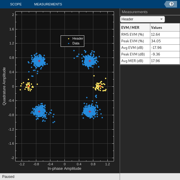
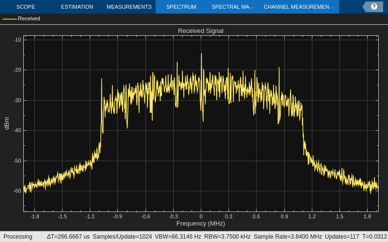
可視化用のスコープは有効にも無効にもできますが、シミュレーションが長い場合はスコープを無効にすることをお勧めします。診断出力テキストの表示を制御するには、必要に応じて詳細を有効または無効にします。各フレームの復号化されたデータを表示するには、出力データ フラグを有効にします。
% The chosen set of OFDM parameters: OFDMParams.FFTLength = 128; % FFT length OFDMParams.CPLength = 32; % Cyclic prefix length OFDMParams.NumSubcarriers = 90; % Number of sub-carriers in the band OFDMParams.Subcarrierspacing = 30e3; % Sub-carrier spacing of 30 KHz OFDMParams.PilotSubcarrierSpacing = 9; % Pilot sub-carrier spacing OFDMParams.channelBW = 3e6; % Bandwidth of the channel 3 MHz % Data Parameters dataParams.modOrder =4; % Data modulation order dataParams.coderate =
"1/2"; % Code rate dataParams.numSymPerFrame =
30; % Number of data symbols per frame dataParams.numFrames =
25; % Number of frames to transmit dataParams.enableScopes =
true; % Switch to enable or disable the visibility of scopes dataParams.verbosity =
false; % Control to print the output diagnostics at each level of receiver processing dataParams.printData =
false; % Control to print the output decoded data
受信機パラメーターの初期化
helperGetRadioParams 関数は、受信機 System object™ ofdmRx を初期化します。OFDM 信号の受信に使用している無線機の名前を変数 radioDevice に割り当てます。受信機のゲインと動作中心周波数を設定します。
helperGetRadioRxObj 関数は、無線受信機 System object を初期化します。
radioDevice ="B210"; % Choose radio device for reception centerFrequency =
3e9; % Center Frequency gain =
60; % Set radio gain
helperOFDMSetParamsSDR 関数は、OFDM シミュレーションに必要な送信機固有のパラメーターおよび送信機と受信機に共通のパラメーターを初期化し、helperGetRadioParams 関数は、受信機 System object™ 無線機に必要なパラメーターを初期化します。
[sysParam,txParam,transportBlk] = helperOFDMSetParamsSDR(OFDMParams,dataParams);
sampleRate                       = sysParam.scs*sysParam.FFTLen;                % Sample rate of signal

ofdmRx = helperGetRadioParams(sysParam,radioDevice,sampleRate,centerFrequency,gain);
Checking radio connections...
[radio,spectrumAnalyze,constDiag] = helperGetRadioRxObj(ofdmRx);
受信機ループの実行
Synchronization
OFDM 受信機は、サンプル バッファーで同期シンボルをチェックし、受信した OFDM 信号内のデータ フレームの開始点を見つけます。受信機は、受信した OFDM 信号を既知の同期シンボルと相関させています。OFDM 受信機は、高い相関ピークを検出すると、同期シンボルの位置をフレームの開始として識別します。
周波数オフセットの推定と補正
OFDM 受信機は、チャネル劣化要因によって OFDM 送信信号に生じた周波数とタイミングのオフセットを推定して修正します。OFDM 受信機は、受信機バッファーで必要なフレーム数をチェックし、各シンボルに対して自動周波数補正を実行します。受信機は、6 つのシンボルから成るグループをスロットと見なし、サブキャリア全体にわたって周波数補正を平均化した後、6 つのシンボルごとに周波数補正を平均化します。受信機は、これらの補正の全体的な平均値を周波数オフセットと見なし、フレーム全体にわたってこの周波数オフセットを補正します。
同期とチャネル劣化要因の修正が正常に完了すると、受信機は基地局にキャンプされているとみなされます。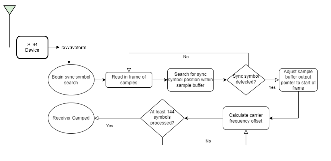
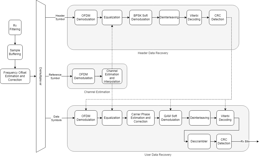
受信機の処理
この処理は、送信機で行われる処理の逆になります。
チャネル推定とイコライゼーション
最初に、OFDM 受信機は、OFDM 復調された参照シンボルに対してチャネル推定を実行します。時間によって変化するフェージングの影響を除去するため、受信機は、隣接するフレームから 2 つの参照シンボルを選択し、2 つの異なる時点でチャネルを推定します。次に、受信機は、2 つの参照シンボル間のチャネル推定値を線形内挿し、ヘッダー シンボルとデータ シンボルのチャネル推定値を取得します。次に、ofdmEqualize 関数は、チャネル推定値を使用して参照シンボルとデータ シンボルをイコライズします。
ヘッダーの復号化
受信機は、ヘッダー シンボルを抽出して復号化し、FFT 長、サブキャリア変調スキーム、符号化率などのデータ シンボル パラメーターを取得します。受信機は、これらのパラメーターを使用してデータ シンボルを復調および復号化します。
データの復号化
共通位相誤差 (CPE) は、すべてのサブキャリアに等しく影響します。OFDM 受信機では、データ シンボル内のパイロット シンボルを使用して CPE が推定されます。helperOFDMRx 関数はデータ シンボルの位相誤差を修正し、qamdemod 関数はデータ サブキャリアを対数尤度比 (LLR) に軟復号化します。
次に、受信機は復調されたビットストリームをデインターリーブし、vitdec 関数はビタビ アルゴリズムを使用して最大尤度復号化を実行します。デスクランブラーは復号化されたビットをデスクランブルします。comm.CRCDetector は巡回冗長検査 (CRC) を計算し、その値と追加された CRC を比較します。
% Clear all the function data as they contain some persistent variables
clear helperOFDMRx helperOFDMRxFrontEnd helperOFDMRxSearch helperOFDMFrequencyOffset;
close all;

errorRate = comm.ErrorRate();
toverflow = 0; % Receiver overflow count
rxObj = helperOFDMRxInit(sysParam);
BER = zeros(1,dataParams.numFrames);
for frameNum = 1:dataParams.numFrames
    sysParam.frameNum = frameNum;
    [rxWaveform, ~, overflow] = radio();

    toverflow = toverflow + overflow;

    % Run the receiver front-end only when there is no overflow
    if ~overflow
        rxIn = helperOFDMRxFrontEnd(rxWaveform,sysParam,rxObj);

        % Run the receiver processing
        [rxDataBits,isConnected,toff,rxDiagnostics] = helperOFDMRx(rxIn,sysParam,rxObj);
        sysParam.timingAdvance = toff;

        % Collect bit and frame error statistics
        if isConnected
            % Continuously update the bit error rate using the |comm.ErrorRate|
            % System object
            berVals = errorRate(...
                transportBlk((1:sysParam.trBlkSize)).', ...
                rxDataBits);
            BER(frameNum) = berVals(1);
            if dataParams.printData
                % As each character in the data is encoded by 7 bits, decode the received data up to last multiples of 7
                numBitsToDecode = length(rxDataBits) - mod(length(rxDataBits),7);
                recData = char(bit2int(reshape(rxDataBits(1:numBitsToDecode),7,[]),7));
                fprintf('Received data in frame %d: %s',frameNum,recData);
            end
        end

        if isConnected && dataParams.enableScopes
            constDiag(complex(rxDiagnostics.rxConstellationHeader(:)), ...
                complex(rxDiagnostics.rxConstellationData(:)));
        end

        if dataParams.enableScopes
            spectrumAnalyze(rxWaveform);
        end
    end
end
Sync symbol found.
Estimating carrier frequency offset ........
Receiver camped.
..................
% Display the mean BER value across all frames
fprintf('Simulation complete!\nAverage BER = %d',mean(BER))
Simulation complete!
Average BER = 0
release(radio);
トラブルシューティング
どのフレームにもデータがない
問題
受信機がどのフレームでもデータを受け取っていない状態が続いています。
考えられる原因
送信機が動作していない
送信機と受信機のゲインが高すぎるか低すぎる
送信機のアンダーランが多すぎる
考えられる解決策
送信機が動作していることを確認する
送信機と受信機のゲインを調整する
フレームの長さを調整し、送信機でのアンダーランが非常に少なくなるようにする。
ヘッダーの CRC が失敗する
問題
同期と受信機のキャンプが成功したにもかかわらず、ヘッダーの CRC チェックが失敗します。
考えられる原因
クロック周波数オフセットの補正が十分でない。
考えられる解決策
周波数補正アルゴリズムは、各フレームの周波数と位相オフセットを測定して補正します。このアルゴリズムは、サブキャリア間隔の半分まで正しいオフセットを推定できます。このエラーを解決するには、周波数オフセットのキャリブレーションを行います。
USRP 無線機の場合、送信機から既知の周波数でトーンを送信し、送信周波数と受信周波数との間のオフセットを測定することで、周波数オフセットを判定できます。測定されたオフセットを、comm.SDRuReceiver 受信機 System object の中心周波数に適用します。
ADALM-Pluto 無線機の場合、Frequency Offset Calibration with ADALM-PLUTO Radio in Simulinkの例を実行して周波数オフセットを取得します。測定されたオフセットを、comm.SDRRxPluto 受信機 System object の中心周波数に適用します。
データの復号化が失敗する
問題
ヘッダー CRC の復号化が成功したにもかかわらず、データの復号化が失敗します。
考えられる原因
受信機でデータがオーバーフローしている
フレームが長すぎるためにチャネルが正しく推定されない。
考えられる解決策
フレーム サイズを調整する
フレームあたりのシンボル数を変更してフレーム長を最小限に抑える。
その他の調査
無線機で外部のクロック ソースまたは GPSDO を使用すると、1.4 MHz などの狭い帯域幅 (LTE 帯域幅)、または 256 などのより高い FFTLength で、15 KHz というより狭いサブキャリア間隔を試すことができます。
この例では、バースト サイズをフレーム数に設定し、無線機でバースト モードを使用してデータを受信します。非バースト モードで無線機を使用することで、データの受信についてさらに詳しく調べることができます。