rcs
Calculate and plot monostatic and bistatic radar cross section (RCS) of platform, antenna, or array
Syntax
Description
[___] = rcs(___,
specifies additional options using one or more name-value
arguments. For a bistatic RCS, specify the TransmitAngle name-value argument
as a 2-by-1 matrix with non-zero values.Name=Value)
Examples
Create a default helix antenna and plot the RCS at 2 GHz.
ant = helix;
rcs(ant,2e9)
Create a default linear array and plot the RCS at 75 MHz in the elevation pane.
array = linearArray;
rcs(array,75e6,0,0:1:360)
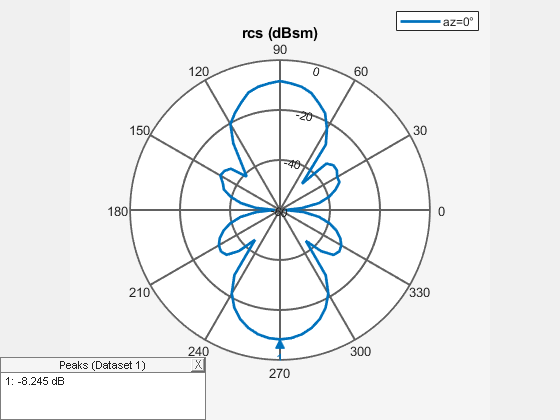
Create a reflector-backed dipole and plot the RCS at 1 GHz in the elevation plane at 90 degree azimuth.
ant = reflector;
rcs(ant,1e9,90,0:1:360)
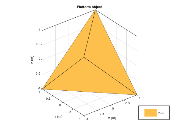
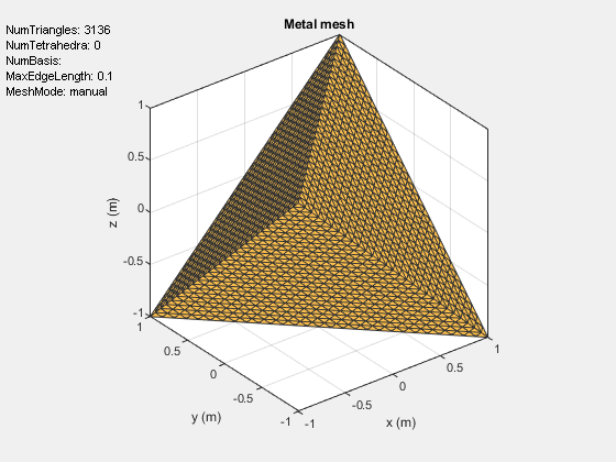
Create a tetrahedron platform from an STL file.
p = platform;
p.FileName = "tetrahedra.stl";
p.Units = "m";
figure
show(p)
Mesh the platform with edge length of 0.1
figure
mesh(p,MaxEdgeLength=0.1)
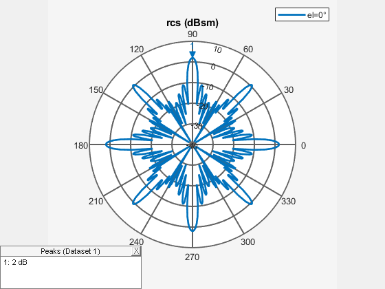
Sweep over the elevation with a vertically polarized E-field. Plot the RCS at 700 MHz in the azimuth plane.
az = 0:1:360;
el = 0;
figure
rcs(p,700e6,az,el)
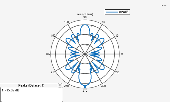
Create a corner reflector-backed antenna.
f = 2e9;
c = design(reflectorCorner,750e6);
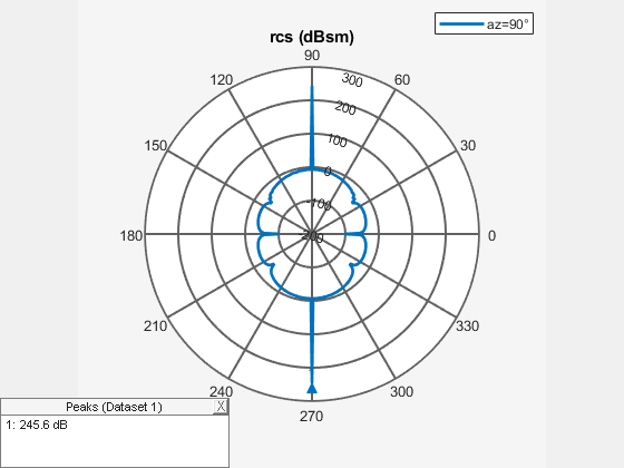
Plot the RCS in the elevation plane.
figure
rcs(c,f,0,0:2:360)
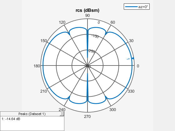
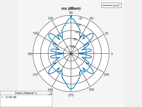
Plot the RCS in the azimuth plane.
figure
rcs(c,f,0:2:360,0)
Calculate bistatic RCS for a default offset cassegrain antenna at a frequency of 14 GHz.
S = rcs(cassegrainOffset,14e9,TransmitAngle=[30;60],ReceiveAngle=[30;45])
S =
-2.9877
This example shows how to calculate and plot the 3-D RCS pattern of a platform.
Import the platform geometry stored in a STL file to workspace using the platform object. Define the azimuth and elevation angles to calculate the RCS. Use parallel pool to expedite the calculations.
p = platform;
p.FileName = "square_plate.stl";
p.Units = 'm'
p =
  platform with properties:

         FileName: "square_plate.stl"
            Units: 'm'
    UseFileAsMesh: 0
             Tilt: 0
         TiltAxis: [1 0 0]
figure
show(p)

az = 0:1:360;
el = -90:1:90;
parfor k = 1:numel(el)
    rcsval(:,k) = rcs(p,9e9,az,el(k));
end
Define the phi and theta angles to plot the RCS pattern. Use the patternCustom function to plot the 3-D RCS pattern.
phi = az';
theta = (90-el);
MagE = rcsval;
P = PatternPlotOptions;
P.MagnitudeScale = [-40 0];
figure
patternCustom(MagE,theta,phi,PatternOptions=P);

Input Arguments
Name-Value Arguments
Output Arguments
More About
Radar Cross Section (RCS) is the measure of scattering cross section of an object interrogated by a plane wave. The assumption of a plane wave implies that the structure is in the far field of the radiator, which is typically a part of the radar system. RCS is a function of the object's shape, the frequency of the radar, the angle of interrogation of the wave, and the object's material parameters. RCS can also be measured in logarithmic units of dBsm, which is dB relative to a 1 m2 reference area.
RCS is calculated using two typical configurations:
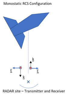
Monostatic
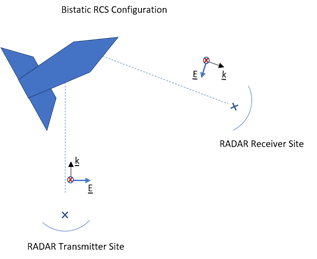
Bistatic
By default, the rcs function calculates a monostatic RCS. To
calculate a bistatic RCS, restrict the "TransmitAngle" to 2-by-1.
The monostatic RCS configuration is characterized by a radar system that transmits a signal and receives the backscattered signal from the object being interrogated at the same site. The source of the transmitted electromagnetic waves and the receiving system for the scattered wave are co-located.
In the bistatic RCS configuration, the radar system consists of a fixed radar transmitting site and a fixed or mobile receiving site captures the backscattered waveform from the object.
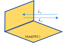
The classic physical optics (PO) formulation does not support multiple reflections from a physical structure illuminated by a plane wave. The PO current density is valid only in the illuminated region of the structure. This formulation does not handle any reflections from the illuminated region that result in secondary illumination of a different region of the structure.
Case 1: When the direction of the incident plane wave results in a reflection back in the direction of the incoming source.
Case 2: When the angle of the incident plane wave causes a second reflection from a different part of the structure, this reflection contributes significantly to the scattered field and is not considered by the PO solver.
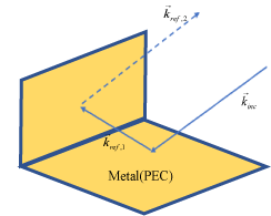
.
References
[1] Gurel, L., H. Bagrci, J. C. Castelli, A. Cheraly, F. Tardivel. "Validation Through Comparison: Measurement and Calculation of the Bistatic Radar Cross Section of a Stealth Target." Radio Science. Vol. 38, Number 3, 2003, pp.12-1 - 12-8.
[2] Rao, S.M., D. R. Wilton, A. W. Glisson. "Electromagnetic Scattering by Surfaces of Arbitrary Shape." IEEE Trans. Antennas and Propagation. Vol. AP-30, Number 3, 1982, pp.409-418.
[3] Jakobus, U., F. M. Landstorfer. "Improved PO-MM Formulation for Scattering from Three-Dimensional Perfectly Conducting Bodies of Arbitrary Shape.." IEEE Trans. Antennas and Propagation. Vol. AP-43, Number 2, 1995, pp.162-169.