3 次元モデリング、CAD ファイル、製造
独自にカスタマイズした 2 次元および 3 次元のジオメトリを作成します。アンテナ設計、大規模構造、PCB 製造用の CAD ファイルのインポートとエクスポートを行います。この任意の素子に対して給電を定義し、解析関数を使用してアンテナまたはアレイを解析します。
PCB アンテナの幾何学的形状を作成して組み合わせます。PCB アンテナのコネクタと製造サービスを選択します。PCB アンテナ製造用のガーバー ファイルを作成します。
カテゴリ
- 3 次元モデリング
形状とブール演算、形状からのアンテナ作成、形状およびアンテナのコンフォーマル アレイ
- CAD ファイルのインポートとエクスポート
光造形法 (STL)、STEP、IGES、glTF、ガーバー ファイル
- PCB アンテナの設計および製造
PCB アンテナ、ガーバー ファイルのライターおよびリーダー、RF コネクタ、製造サービス
注目の例

Model Coaxial Gap Feed for Probe-Fed Patch Antenna
Comparison of a standard delta-gap probe feed model and a finite-gap coaxial feed model for a patch antenna.
Design and Analyze Perforated Horn Antenna for RF Applications
Design a perforated horn antenna suited for RF applications using 3-D modeling features of the Antenna Toolbox™.

Train Machine Learning Model for Analysis of Custom Antenna
Apply machine learning to antenna analysis: a general recipe that you can use to train machine learning models to characterize antenna structures modeled and simulated in Antenna Toolbox™.

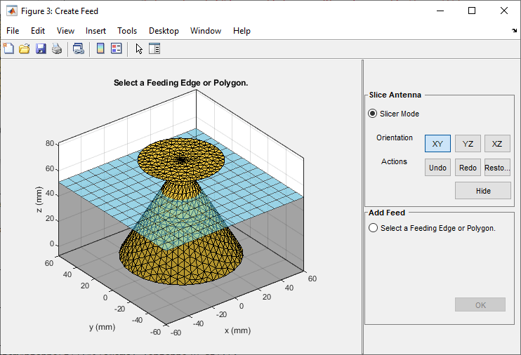
Design And Analyze Spherically Capped Biconical Antenna
Design spherically capped bicone antenna using 3-D modeling features and analyze its performance in 900 MHz to 15 GHz frequency range.

Analysis of Ultrawideband Trident Inset-Fed Monopole Antenna with Conical Ground
Design trident inset-fed monopole antenna using 3-D modeling features and analyze its performance over a conical ground plane.

Design and Analysis of Diamond-Shaped PCB Antenna for Ultra-Wideband Applications
Design and ultra‑wideband analysis of a diamond‑shaped monopole antenna with a modified ground plane, modeled on an FR4 substrate and operating from 100 MHz to 15 GHz, highlighting its compact, low‑power characteristics suitable for modern UWB applications.

5G 基地局向け直列給電パッチ アンテナ アレイの設計
5G 基地局用途向けに 28 GHz で動作する 8 行 8 列直列給電パッチ アンテナ アレイを設計および解析し、水平ビーム ステアリングによって指向性カバレッジを実現する。

USB ドングルおよび BLE 用途向けの PCB アンテナ
2.4 GHz における USB ドングルおよび BLE 用途向けの PCB アンテナの設計および解析を行う。

Miniaturize Patch Antennas Using Metamaterial-Inspired Technique
Design and performance evaluation of a highly miniaturized 2.4 GHz patch antenna using a complementary split‑ring resonator (CSRR) loading technique that reduces the patch radius from 23.1 mm to 6 mm.

Design and Analysis of Compact Ultra-Wideband MIMO Antenna Array
Design and analysis of a compact ultra‑wideband MIMO antenna array operating from 3.1 to 10.6 GHz to address multipath fading and enhance channel capacity in UWB systems.

PCB アンテナ デザイナーを使用した設計と解析
1 行 2 列の H ノッチ直線アンテナ アレイを設計、検証、解析、およびエクスポートする。

Create Antenna Model from Gerber Files
Create an antenna model from Gerber files and subsequently analyze the antenna. The Gerber file format is used in printed circuit board (PCB) manufacturing and is defined in the RS-274X standard which is the newer extended Gerber format. The Antenna Toolbox™ supports the newer RS-274X format both to generate Gerber files from an antenna model as well as to create an antenna model from a set of Gerber files.
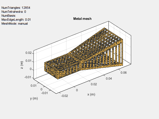
Import and Analyze Custom 3-D Antenna Geometry
Simulate a 3-D custom antenna geometry from an STL (stereolithography) file. An STL file is a tessellation of a structure in 3-D space using triangles. To simulate a 3-D custom antenna geometry, use the customAntennaStl object. This object allows you to simulate a custom 3-D geometry from an *.stl file.
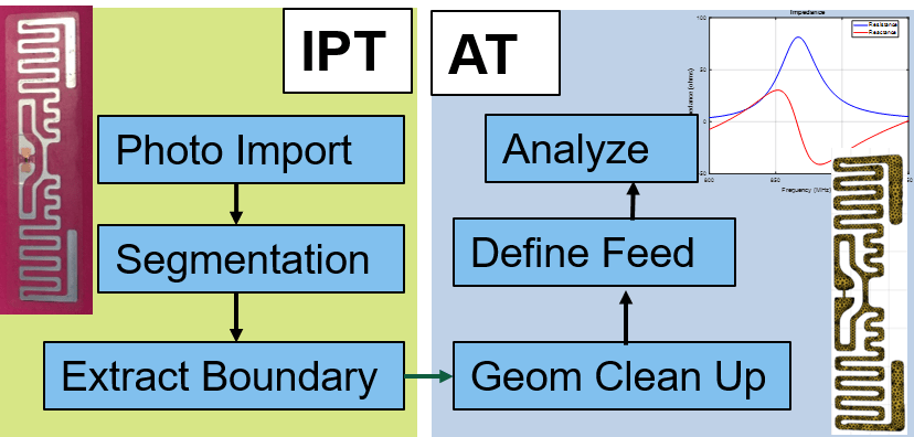
Antenna Model Generation and Full-Wave Analysis From Photo
The process of using a photograph of a planar antenna to generate a viable antenna model and its subsequent analysis for port, surface and field characteristics. The Image Segmenter app is used to perform segmentation on the image of an RFID tag, and the resulting boundaries are used to set up the antenna model in Antenna Toolbox™. An initial impedance analysis is done over a frequency range to understand the port characteristics of the antenna. After determining the resonant frequency, the current and far-field pattern are calculated and plotted.
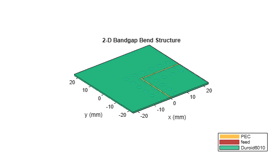
Model and Analyze Planar Photonic Band Gap Structure
Create and analyze microwave planar Photonic Band Gap (PBG) structures using Antenna Toolbox™. Photonic Band Gap structures consist of a periodic lattice which provides effective and flexible control of the Electromagnetic wave propagation in one or multiple directions. Microwave planar PBG structures were first introduced around the year 2000 by Prof. Itoh and his group. These structures create a stop band over a certain frequency range and are easy to implement by cutting periodic patterns on the metal ground plane.
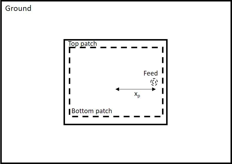
Modeling and Analysis of Probe-Fed Stacked Patch Antenna
The steps to model and analyze a probe-fed stacked patch antenna. The standard rectangular microstrip patch antenna has a narrow impedance bandwidth typically less than 5%. The stacked patch configuration is one of the ways of increasing the impedance bandwidth of these antennas to be greater than 25% [1]. There are different ways of designing stacked patches, primarily differing in the way their feed is designed [2]. The two types of feeding mechanisms are probe-feed and aperture coupled. These two mechanisms have a role in the impedance bandwidth behavior as well as the radiation characteristics of the antenna.

Model and Analyze Dual Polarized Patch Microstrip Antenna
Design and measure a wideband dual polarized microstrip antenna that finds its use at the base station of a cellular system. In order to achieve the wideband characteristics, this design considers a slot coupled patch antenna structure.

Design Microstrip Patch at 77 GHz for Automotive Radar Receiver
Create, model, and analyze an inset-fed microstrip patch antenna at high frequencies. As the frequency of operation increases to millimeter waves, the antenna sizes decrease and the antennas are fabricated on printed circuit boards (PCBs). Such printed antennas are of light weight, are inexpensive, easy to integrate, and are widely used as components in a radar. The antenna designed in this example operates at a frequency of 77 GHz and is used in an automotive radar receiver.