5G 基地局向け直列給電パッチ アンテナ アレイの設計
この例では、28 GHz の直列給電パッチ アンテナ アレイの設計および解析を行う方法を説明します。このアレイは、8 行 8 列構成で配置された 64 個のアンテナ素子をもち、28 GHz の 5G モバイル基地局アンテナとして使用されます。フェーズド アレイは、ビームを水平軸に沿って誘導し、さまざまな方向をカバーします。

変数の作成
[2] に従い、変数を作成して値を割り当てます。
Wp = 3.539e-3;
Wc = 0.494e-3;
Lc = 3.539e-3;
Wm = 2.727e-3;
Lm = 0.6269e-3;
Wf = 0.72e-3;
Lf = 2.215e-3;
ジオメトリの作成
antenna.Rectangle 形状オブジェクトを使用して構造内のすべての矩形を作成し、それらを結合します。show 関数を使用して構造を可視化します。
a = antenna.Rectangle(Length=Lf,Width=Wf,Center=[Lf/2,0]);
transVec = Lf;
for i=1:7
b = antenna.Rectangle(Length=Wp,Width=Wp,Center=[transVec+Wp/2,0]);
transVec = transVec + Wp;
c = antenna.Rectangle(Length=Lc,Width=Wc,Center=[transVec+Lc/2,0]);
transVec = transVec + Lc;
a = a + b + c;
end
last = antenna.Rectangle(Length=Wp,Width=Wp,Center=[transVec+Wp/2,0]);
lastsub = antenna.Rectangle(Length=Lm,Width=Wm,Center=[transVec+Lm/2,0]);
last = last - lastsub;
conn = antenna.Rectangle(Length=Lc,Width=Wc,Center=[transVec+Lc/2,0]);
a = a + last + conn;
figure
show(a)

PCB ボードの設計
pcbStack オブジェクトを使用して、PCB スタックを作成します。グランド プレーン層と誘電体層を作成し、グランド プレーンと同じ形状になるように BoardShape を設定します。PCB スタックを可視化します。
ant = pcbStack;
gnd = antenna.Rectangle(Length=57e-3,Width=10e-3,Center=[57e-3/2,0]);
d = dielectric("Teflon");
d.EpsilonR = 2.2;
ant.BoardThickness = 0.254e-3;
d.Thickness = ant.BoardThickness;
ant.Layers={a,d,gnd};
ant.BoardShape = gnd;
ant.FeedDiameter = Wf/2;
ant.FeedLocations = [0,0,1,3];
figure
show(ant)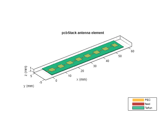
アレイ性能の解析
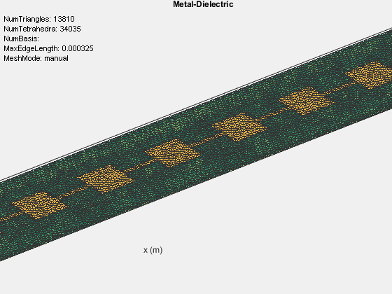
mesh 関数を使用してメッシュを手動で生成し、MaxEdgeLength プロパティを 0.4 mm に設定して、必ず 1 波長あたり 30 個の三角形が存在するようにします。
figure
mesh(ant,MaxEdgeLength=0.325e-3);
zoom(2.55)
構造の解を求めるのに必要なメモリを計算するには、memoryEstimate 関数を使用します。
memEst = memoryEstimate(ant,28e9)
memEst =
'49 GB'
非常に多くのメモリを必要とするため、S パラメーターを計算してアンテナ パターンをプロットするのにかかる時間は非常に長くなります。この例には、リターン ロスとパターン データの計算が格納された MAT ファイルが含まれています。結果を計算するのに使用したコードは、リターン ロスとパターン データの計算のセクションで入手できます。64 GB の RAM と Intel(R) Xeon(R) W-2133 CPU プロセッサを搭載したマシンでは、1 つの周波数について解を求めるのに約 50 分かかります。
MAT ファイルを読み込み、rfplot 関数を使用してリターン ロスをプロットします。
load seriesPatchData.mat
figure
rfplot(out);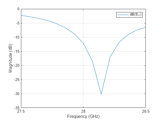
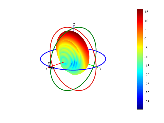
patternCustom を使用して、アンテナの 2 次元または 3 次元の放射パターンをプロットします。
phi = az';
theta = (90-el);
MagE = pat';
figure
patternCustom(MagE,theta,phi);
パターンの乗算を使用した放射パターンのプロット
MoM ソルバーを使用して構造全体の解を求める代わりに、パターンの乗算を使用して 8 行 8 列のアレイの放射パターンをプロットします。パターンの乗算を使用するには、Phased Array System Toolbox™ のライセンスが必要です。
phased.CustomAntennaElement System object™ を使用し、読み込んだ MAT ファイルのパターン データに基づいてカスタム アンテナ素子を構築します。
antenna = phased.CustomAntennaElement;
antenna.FrequencyVector = [0 28e9];
antenna.AzimuthAngles = az;
antenna.ElevationAngles = el;
antenna.MagnitudePattern = pat;
antenna.PhasePattern = zeros(size(pat));
phased.ULA System object™ を使用して、8 行 8 列のアレイを作成します。カスタム素子をアレイの素子として指定します。素子の数を 8 に設定し、素子の間隔を 3.5 mm に設定します。
array = phased.ULA;
array.Element = antenna;
array.NumElements = 8;
array.ElementSpacing = 3.5e-3;
パターン乗算
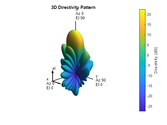
pattern 関数を使用して、3 次元放射パターンをプロットします。
figure
pattern(array,28e9)
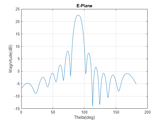
pattern 関数を使用して、E 平面の放射パターンをプロットします。
pat1 = pattern(array,28e9,0,0:1:90,CoordinateSystem="rectangular");
pat2 = pattern(array,28e9,180,0:1:90,CoordinateSystem="rectangular");
data1 = [pat1; flip(pat2)];
figure
plot(data1);
grid on;
xlabel("Theta(deg)");
ylabel("Magnitude(dB)");
title("E-Plane");
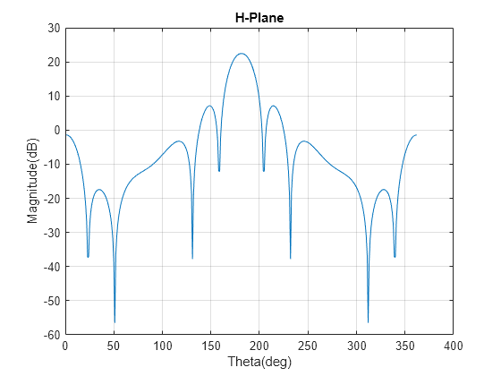
pattern 関数を使用して、H 平面の放射パターンをプロットします。
pat3 = pattern(array,28e9,90,-90:1:90,CoordinateSystem="rectangular");
data2 = [pat3;flip(pat3)];
figure
plot(data2);
grid on;
xlabel("Theta(deg)");
ylabel("Magnitude(dB)");
title("H-Plane");
リターン ロスとパターン データの計算
この例で使用した 'seriesPatchData.mat' ファイルは、次のコードを使用して生成しました。
type RLpatDataComputation.mout = sparameters(ant,linspace(27.5e9,28.5e9,11)); figure; rfplot(out); figure; pattern(ant, 28e9) figure; impedance(ant,linspace(27.5e9,28.5e9,11));
参考文献
[1] “EM Simulation of 28 GHz Series-Fed Patch Antenna Array for 5G | 2019-02-01 | Microwave Journal.” Accessed January 21, 2022. https://www.microwavejournal.com/articles/31731-em-simulation-of-28-ghz-series-fed-patch-antenna-array-for-5g.
[2] Ishfaq, Muhammad Kamran, Tharek Abd Rahman, Yoshihide Yamada, and Kunio Sakakibara. “8×8 Phased Series Fed Patch Antenna Array at 28 GHz for 5G Mobile Base Station Antennas.” In 2017 IEEE-APS Topical Conference on Antennas and Propagation in Wireless Communications (APWC), 160–62. Verona, Italy: IEEE, 2017. https://doi.org/10.1109/APWC.2017.8062268.