NR SRS の構成
この例では、TS 38.211 の Section 6.4.1.4 [1] で定義されているサウンディング基準信号 (SRS) を生成する方法を示します。これには、SRS の構成、シンボルとインデックスの生成、OFDM リソース グリッド マッピング、および SRS 波形の生成が含まれます。この例では、SRS を周波数でポジショニングして設定するために適切なパラメーターを選択する方法を示します。
全帯域送信: 利用可能なすべての帯域幅にわたる SRS を生成します。
周波数ホッピング送信: 異なる周波数ホッピング パターンを使用して、周期的および非周期的な SRS 送信を生成します。
マルチユーザー送信: 時間シフト、周波数シフト、およびサイクリック シフトを使用して直交 SRS を生成します。
はじめに
サウンディング基準信号は、チャネル品質の推定や同期などのアップリンク チャネルのサウンディングのためにユーザー端末 (UE) によって使用されるアップリンク物理量信号です。復調基準信号 (DM-RS) とは異なり、SRS は物理アップリンク チャネルには関連付けられず、アップリンク チャネルに依存するスケジューリングとリンク適応をサポートします。SRS は次の点で役立ちます。
コードブックベースの閉ループ空間多重化。
アップリンク送信タイミングの制御。
マルチユーザー MIMO 設定における相反性ベースのダウンリンク プリコーディング。
物理チャネルと基準信号の疑似コロケーション。
周波数ポジショニング
このセクションでは、周波数領域における SRS の位置を構成し、SRS に割り当てられる帯域幅を決定する方法を示します。
帯域幅 15 MHz のキャリアを 15 kHz のサブキャリア間隔 (SCS) で構成します。
carrier = nrCarrierConfig; carrier.NSizeGrid =79; % Bandwidth in RB carrier.SubcarrierSpacing =
15;
帯域幅構成パラメーター CSRS および BSRS は、SRS に割り当てられる帯域幅を制御します。通常、SRS は CSRS が増えるにしたがって増加し、BSRS が増えるにしたがって減少します。次の対話型コントロールを使用して、SRS 帯域幅を構成します。
srs = nrSRSConfig; srs.CSRS =10; % Bandwidth configuration C_SRS (0...63) srs.BSRS =
1; % Bandwidth configuration B_SRS (0...3)
SRS の周波数位置を変更するには、FrequencyStart と NRRC の値を変更します。FrequencyStart は、NRRC = 0 の場合の、キャリアの原点を基準とした RB 内の SRS の周波数原点を指定します。
srs.FrequencyStart =30; % Frequency position of the SRS in carrier in RB (0...271) srs.NRRC =
0; % Frequency domain position in blocks of 4 PRB (0...67) hSRSGrid(carrier,srs,1,true); % Create and display a single-slot resource grid containing SRS title(['Resource Grid Containing SRS. NRRC = ' num2str(srs.NRRC)]); hSRSAnnotations(carrier,srs);
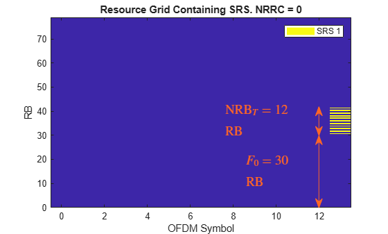
この図は、SRS を含む単一スロットの OFDM リソース グリッドを示しています。CSRS = 10 および BSRS = 1 の場合、SRS の周波数位置は、NRRC が範囲 (3...5) にあるときは だけシフトし、NRRC が範囲 (6...8) にあるときは だけシフトします。NRRC が 9 である場合、SRS は初期位置 (FrequencyStart) に戻ります。 は、送信ごとに SRS に割り当てられるリソース ブロック (RB) の数です。
次の図は、CSRS = 10 および BSRS = 1 の場合について、上記で紹介した概念を示したものです。
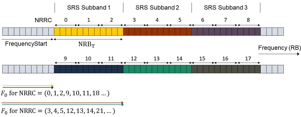
NRRC は、4 つの RB の数として指定する追加の周波数オフセットであり、上位レイヤー パラメーター freqDomainPosition に対応します (TS 38.331 の Section 6.3.2 SRS-Config [2] を参照)。NRRC の値が と の間である場合、SRS の周波数位置は だけシフトされます。ここで、 は整数です。TS 38.211 の Section 6.4.1.4 では、 が () として参照されています。詳細については、nrSRSConfig 構成オブジェクトの NRBPerTransmission プロパティを参照してください。
次の式は周波数における SRS の基準点を求めます。
は、パラメーター NRRC を使用して SRS を配置できる SRS サブバンド (サイズ の周波数帯域) の数を示します。 を計算するには、SRS 帯域幅構成テーブルを使用できます (TS 38.211 の Table 6.4.1.4.3-1 を参照)。このテーブルには、nrSRSConfig オブジェクトの BandwidthConfigurationTable プロパティからアクセスすることもできます。
csrs = srs.CSRS;
disp(nrSRSConfig.BandwidthConfigurationTable(csrs+(0:2) + (csrs==0),:));
    C_SRS    m_SRS_0    N_0    m_SRS_1    N_1    m_SRS_2    N_2    m_SRS_3    N_3
    _____    _______    ___    _______    ___    _______    ___    _______    ___

      9        32        1       16        2        8        2        4        2
     10        36        1       12        3        4        3        4        1
     11        40        1       20        2        4        5        4        1
最初の列には、パラメーター CSRS の取り得る値が含まれています。CSRS = 10 および BSRS = 1 の場合、一意の SRS サブバンドの数は です (ここで、 および )。
% Calculate and display the number of SRS subbands configurable by NRRC
NSBTable = hSRSNumberOfSubbandsOrHoppingPatterns(srs);

fprintf('Number of SRS subbands (NRRC < %d):  %d', NSBTable*srs.NRBPerTransmission/4,NSBTable);
Number of SRS subbands (NRRC < 9): 3
% Calculate the frequency origin of the first SRS symbol
f0 = hSRSFrequencyOrigin(srs);
fprintf('The frequency origin of the SRS is F0 = %d RB.', f0);
The frequency origin of the SRS is F0 = 30 RB.
nrSRSIndices の info 出力を使用して SRS の周波数位置を確認します。
[~,info] = nrSRSIndices(carrier,srs);
display(info.PRBSet(1))
30
CSRS の値について、NRRC を使用して SRS を割り当てることができる周波数帯域は です。CSRS = 10 の場合、SRS は のときにラップアラウンドし、 と同じ周波数位置になります。
fprintf('The SRS frequency range is limited to the range (%d,%d) RB for the current value of CSRS (%d).',srs.FrequencyStart,srs.FrequencyStart + NSBTable*srs.NRBPerTransmission,srs.CSRS);The SRS frequency range is limited to the range (30,66) RB for the current value of CSRS (10).
スロット内の周波数ホッピングが有効になっている場合、FrequencyOrigin の計算はスロットの最初の SRS シンボルに対してのみ有効です。周波数ホッピング SRS の場合、nrSRSIndices 関数の出力 info.PRBset または info.SubcarrierOffset を使用して、後続のシンボルの周波数位置を決定します。
fprintf('The frequency origin of the SRS is F0 = %d RB.',info.PRBSet(1));The frequency origin of the SRS is F0 = 30 RB.
全帯域幅構成
このセクションでは、キャリアの適切な SRS 帯域幅パラメーターを計算して、全帯域 SRS 送信を構成して生成する方法を示します。
帯域幅 10 MHz のキャリアを 15 kHz の SCS で構成します。
carrier = nrCarrierConfig; carrier.NSizeGrid =52; carrier.SubcarrierSpacing =
15;
帯域幅構成パラメーター CSRS、BSRS、および BHop は、SRS に割り当てられる帯域幅を制御します。全帯域 SRS を構成するには、CSRS = 14 および BSRS = 0 に設定します。
srs = nrSRSConfig; srs.CSRS =13; % Bandwidth configuration C_SRS (0...63) srs.BSRS =
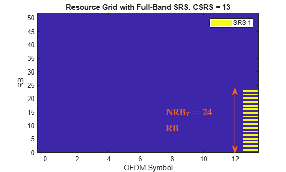
1; % Bandwidth configuration B_SRS (0...3) hSRSGrid(carrier,srs, 1, true); % Create and display a single-slot resource grid containing SRS title(['Resource Grid with Full-Band SRS. CSRS = ' num2str(srs.CSRS)]); hSRSAnnotations(carrier,srs);
SRS 周波数割り当ての場合、CSRS、BSRS、および BHop の適切な値は SRS 帯域幅構成テーブルで確認できます (TS 38.211 の Table 6.4.1.4.3-1 を参照)。あるいは、nrSRSConfig.BandwidthConfigurationTable を使用することで、このテーブルに簡単にアクセスして表示できます。
% To display relevant rows of the bandwidth configuration table, calculate the value of CSRS for a full band SRS
[csrs,bsrs] = hSRSBandwidthConfiguration(srs,carrier.NSizeGrid);

% Display bandwidth configuration table
disp(nrSRSConfig.BandwidthConfigurationTable(csrs+(0:2) + 1*(csrs==0),:));
    C_SRS    m_SRS_0    N_0    m_SRS_1    N_1    m_SRS_2    N_2    m_SRS_3    N_3
    _____    _______    ___    _______    ___    _______    ___    _______    ___

     13        48        1       24        2       12        2        4        3
     14        52        1        4       13        4        1        4        1
     15        56        1       28        2        4        7        4        1
m_SRS_b (b = 0...3) というラベルの付いた列には、パラメーター b = BSRS かつ非ホッピング構成の SRS に割り当てられた RB の数が含まれます。C_SRS = 14 に対応する行には、RB の数 m_SRS_0 = 52 が含まれており、これはキャリア帯域幅に最も近い値です。したがって、パラメーター CSRS = 14 および BSRS = 0 は、現在のキャリア構成に対して全帯域 SRS 送信を構成します。この例では、帯域幅構成テーブルを使用して、キャリア内の SRS 帯域幅を最大化する CSRS と BSRS の値を計算します。
fprintf('For a full-band SRS in a carrier bandwidth of %d RB, set CSRS = %d and BSRS = %d.',carrier.NSizeGrid,csrs,bsrs);For a full-band SRS in a carrier bandwidth of 52 RB, set CSRS = 14 and BSRS = 0.
SRS の読み取り専用プロパティ NRBPerTransmission を使用して、生成された SRS がキャリア帯域幅に適合していることを確認できます。
fprintf('The SRS bandwidth (%d RB) is lower than or equal to the carrier bandwidth (%d RB).',srs.NRBPerTransmission,carrier.NSizeGrid);The SRS bandwidth (24 RB) is lower than or equal to the carrier bandwidth (52 RB).
周波数ホッピング構成
マルチシンボルおよびマルチスロットの SRS 送信に対しては、それぞれスロット内およびスロット間の周波数ホッピングを構成できます。OFDM シンボルごとの瞬時帯域幅は SRS OFDM シンボル全体で一定であり、SRS がホップする帯域幅よりも小さくなります。
帯域幅 15 MHz のキャリアを 15 kHz の SCS で構成します。
carrier = nrCarrierConfig; carrier.NSizeGrid =79; carrier.SubcarrierSpacing =
15;
スロット端に 4 シンボルの SRS を作成します。スロット内の連続する等しい SRS 送信 (OFDM シンボル) の数を示す繰り返し係数を選択します。周波数ホッピング構成の場合、Repetition は SRS シンボルの数よりも小さくしなければなりません。
srs = nrSRSConfig; srs.NumSRSSymbols =4; srs.Repetition =
1; srs.SymbolStart =
10; % Time-domain position of the SRS in the slot. (8...13) for normal cyclic prefix (CP) and (6...11) for extended CP
Downlink control information (DCI) は、上位レイヤー パラメーター resourceType を使用して非周期的な SRS 送信をトリガーできます (TS 38.331 の Section 6.3.2 SRS-Config を参照)。非周期的 SRS リソース タイプの場合、周波数ホッピング パターンはスロットごとにリセットされるため、スロット間周波数ホッピングを有効にするには periodic または semi-persistent の SRS リソース タイプを選択し、無効にするには aperiodic を選択します。SRSPeriod プロパティを使用して、SRS 送信のスロット単位の周期とオフセットを構成できます。aperiodic リソース タイプの場合、パラメーター SRSPeriod は、非周期 SRS 送信をトリガーする DCI 信号の周期とオフセットを制御します。
srs.ResourceType ="periodic"; srs.SRSPeriod = [
2 0]; % Periodicity in slots (1,2,4,5,8,10,...) srs.SRSPeriod(2) =
0; % Offset in slots must be smaller than the periodicity
次の対話型コントロールを使用してホッピング構成を選択し、OFDM リソース グリッドの変更を確認します。
srs.CSRS =19; % Bandwidth configuration C_SRS (0...63) srs.BSRS =
2; % Bandwidth configuration B_SRS (0...3) srs.BHop =
0; % Frequency hopping configuration (0...3). Set BHop >= BSRS to disable frequency hopping srs.NRRC =
14; % Frequency domain position in blocks of 4 PRB (0...67) % Create and display a multi-slot resource grid containing SRS duration = 2*srs.SRSPeriod(1); % Transmission length in slots hSRSGrid(carrier,srs, duration, true); title('Carrier Grid Containing Frequency-Hopping SRS')
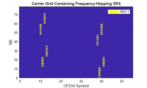
SRS シンボルがホップする帯域幅は、CSRS の値が増えるにしたがって増加し、BHop が増えるにしたがって減少します (BHop = BSRS によってホッピングが無効になるまで)。BSRS を増やすと、OFDM シンボルごとの割り当て帯域幅 (プロパティ NRBPerTransmission) が減少し、スロット内周波数ホッピングも減少します。周波数ホッピングを無効にするには、BHop >= BSRS となるように設定します。非ホッピング構成の場合、CSRS と BSRS の役割は類似しており、割り当てられた帯域幅は CSRS が増えるにしたがって増加し、BSRS が増えるにしたがって減少します。
帯域幅構成テーブル (TS 38.211 の Table 6.4.1.4.3-1) を使用して、SRS パラメーター NRRC で構成可能な異なる周波数ホッピング パターンの数を として計算できます。周波数ホッピング パターンは、 の場合に繰り返されます。
N = hSRSNumberOfSubbandsOrHoppingPatterns(srs);

if srs.BHop < srs.BSRS && srs(1).NRB > 16 % Number of unique frequency-hopping patterns
    fprintf('Number of unique frequency-hopping patterns (configurable by NRRC < %d): %d.',N*srs.NRBPerTransmission/4,N);
else % Number of unique SRS subbands
    fprintf('Number of unique SRS subbands (configurable by NRRC < %d):  %d.',N*srs.NRBPerTransmission/4,N);
end
Number of unique frequency-hopping patterns (configurable by NRRC < 18): 6.
帯域幅構成パラメーターを CSRS = 20, BSRS = 2、および BHop = 1 に設定します。条件 BHop < BSRS は周波数ホッピングを保証するものではありません。ただし、その逆は当てはまります。つまり、BHop >= BSRS は、常に周波数ホッピングを無効にします。帯域幅構成テーブルの パラメーターを使用し、条件 を評価することで、SRS 帯域幅構成 (CSRS、BSRS、BHop) がいつ周波数ホッピングを生成するかを判断できます。
isFreqHoppingConfiguration = hSRSNumberOfSubbandsOrHoppingPatterns(srs) > 1;
disp(['Frequency hopping is' repmat(' not',1,~isFreqHoppingConfiguration) ' enabled.'])
Frequency hopping is enabled.
周波数ホッピングの場合、読み取り専用プロパティ NRB は SRS がホップする帯域幅を指定し、NRBPerTransmission は SRS OFDM シンボルごとに割り当てられる瞬時帯域幅を指定します。
t = table([srs.NRB; srs.NRBPerTransmission],'RowNames', {'Freq-Hopping bandwidth','Instantaneous bandwidth'},'VariableNames',"NRB");
disp(t)
                               NRB
                               ___

    Freq-Hopping bandwidth     72
    Instantaneous bandwidth    12
マルチユーザー構成
このセクションでは、マルチユーザー設定に適した複数の SRS 送信を構成する方法について説明します。時間領域、周波数領域、およびシーケンス領域のパラメーターを使用して、直交 (干渉のない) SRS 送信のセットを作成できます。
時間領域直交 SRS
時間領域直交 SRS 送信は複数の方法で作成できます。以下は例です。
プロパティ
SRSPeriodを使用して、各 SRS に対して異なるスロット周期とオフセットを構成する。プロパティ
SymbolStartを使用して、各 SRS に対して異なるシンボル単位の時間領域割り当てを構成する。
帯域幅 10 MHz のキャリアを 15 kHz の SCS で構成します。
carrier = nrCarrierConfig; carrier.NSizeGrid =52; carrier.SubcarrierSpacing =
15;
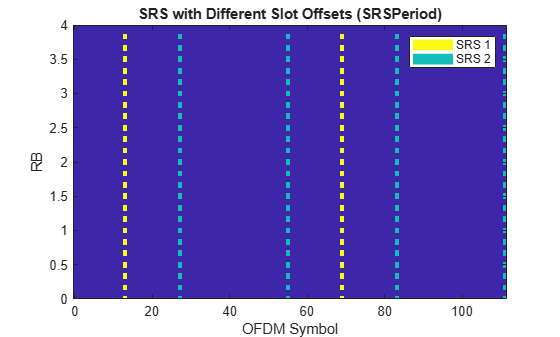
スロットの周期性とオフセットを指定して、直交 SRS 送信を作成します。
最初の SRS 構成:
srs = nrSRSConfig; srs(1).SRSPeriod = [1 0]; srs(1).SRSPeriod(1) =4; % Slot periodicity and offset srs(1).SRSPeriod(2) =
0; % Slot offset of first SRS
2 番目の SRS 構成:
srs(2) = srs(1); % Create a copy of the configured SRS srs(2).SRSPeriod(1) =2; % Periodicity in slots srs(2).SRSPeriod(2) =
1; % Offset in slots
以下の図は、構成された SRS 送信を含む OFDM リソース グリッドを示しています。
hSRSGrid(carrier,srs,srs(1).SRSPeriod(1)*2, true); % Generate a multi-slot resource grid containing SRS
title('SRS with Different Slot Offsets (SRSPeriod)')
ylim([0 srs(1).NRBPerTransmission]);
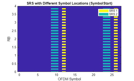
直交 SRS 送信を作成するには、SRS シンボルの数とスロット内の位置を指定します。
最初の SRS 構成:
srs = nrSRSConfig; srs(1).NumSRSSymbols =1; % Number of SRS symbols in a slot (1,2,4) srs(1).SymbolStart =
12; % Time-domain position of the SRS in the slot. (8...13) for normal cyclic prefix (CP) and (6...11) for extended CP
2 番目の SRS 構成:
srs(2) = srs(1); % Create a copy of the configured SRS srs(2).NumSRSSymbols =2; srs(2).SymbolStart =
9;
以下の図は、SRS 送信を含む OFDM リソース グリッドを示しています。
hSRSGrid(carrier,srs, 2, true); % Generate and display a 2-slot resource grid containing SRS
title('SRS with Different Symbol Locations (SymbolStart)');
ylim([0 srs(1).NRBPerTransmission]);
周波数領域直交 SRS
周波数領域直交 SRS 送信は、次のように複数の方法で作成できます。
プロパティ
KBarTCを使用して、各 SRS に対して異なるコム オフセットを構成する。CSRS、BSRS、BHop、およびNRRCを使用して、異なる周波数ホッピング パターンを構成する。
帯域幅 10 MHz のキャリアを 15 kHz の SCS で構成します。
carrier = nrCarrierConfig; carrier.NSizeGrid =52; carrier.SubcarrierSpacing =
15;
直交 SRS 送信を作成するには、コム番号とオフセットを指定します。
最初の SRS 構成:
srs = nrSRSConfig; srs(1).KTC =2; % Comb number (2,4). It indicates the allocation of the SRS every KTC subcarriers srs(1).KBarTC =
1; % Comb offset (0...KTC-1)
2 番目の SRS 構成:
srs(2) = srs(1); % Create a copy of the configured SRS srs(2).KTC =4; srs(2).KBarTC =
0;
以下の図は、SRS 送信を含む OFDM リソース グリッドを示しています。
hSRSGrid(carrier,srs,2,true);
title('SRS with Different Comb Offsets (KBarTC)')
ylim([0 srs(1).NRBPerTransmission]);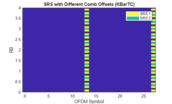
異なる周波数ホッピング パターンを使用して、周波数領域直交 SRS 構成を作成します。
srs = nrSRSConfig; srs.NumSRSSymbols =4; % Number of SRS symbols in a slot srs.SymbolStart =
8; % Allocate SRS in OFDM symbols 10:13
目的の帯域幅構成パラメーター、リソース タイプ、および繰り返し係数を選択します。
srs.CSRS =10; % Bandwidth configuration C_SRS (0...63) srs.BSRS =
2; % Bandwidth configuration B_SRS (0...3) srs.BHop =
0; % Frequency hopping configuration (0...3). Set BHop >= BSRS to disable frequency hopping srs.ResourceType =
"periodic"; % ('periodic','semi-persistent','aperiodic') srs.Repetition =
1; % Number of equal consecutive SRS transmissions (1,2,4). It must be lower than NumSRSSymbols
この例では、NRRC で構成できる直交 SRS シーケンスの数を計算し、周波数がオーバーラップしない SRS 構成を作成します。以下の図は、SRS 送信を含む OFDM リソース グリッドを示しています。
NRRC = num2cell(hNRRCSet(srs));
srs(2:length(NRRC)) = srs(1); % Create N-1 copies of the configured SRS
[srs(:).NRRC] = deal(NRRC{:}); % Assign the appropriate NRRC to each SRS configuration

hSRSGrid(carrier,srs, 3, true); % Generate and display a 3-slot resource grid containing SRS
title('SRS with Different Frequency-Hopping Patterns');
ylim([0 srs(1).NRBPerTransmission*hSRSNumberOfSubbandsOrHoppingPatterns(srs(1))]);
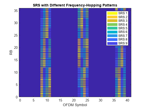
N = hSRSNumberOfSubbandsOrHoppingPatterns(srs(1));
if srs(1).BHop < srs(1).BSRS % Frequency-hopping cases
    fprintf('Number of unique frequency-hopping patterns (configurable by NRRC < %d): %d.', N*srs(1).NRBPerTransmission/4, N);
else
    fprintf('Number of unique subbands (configurable by NRRC < %d):  %d.', N*srs(1).NRBPerTransmission/4,N);
end
Number of unique frequency-hopping patterns (configurable by NRRC < 9): 9.
SRS 送信は、Repetition 係数と ResourceType に関係なくオーバーラップしないことに注意してください (aperiodic の場合、スロット間周波数ホッピングは無効になります)。BHop >= BSRS となるように設定して周波数ホッピングを無効にし、各 SRS が依然として異なるサブバンドに割り当てられていることを確認します。
サイクリックシフト直交 SRS
このセクションでは、同じ時間と周波数リソース (OFDM シンボルとサブキャリア) に割り当てられるが時間領域のサイクリック シフトが異なる複数の SRS を生成します。Zadoff-Chu シーケンスの特性により、この構成では直交 SRS が生成されます。構成された SRS 間の直交性を証明するために、このセクションでは CP-OFDM 変調を実行し、時間領域波形の相互相関を計算します。
% Configure a 10 MHz bandwidth carrier with 15 kHz SCS.
carrier = nrCarrierConfig;
carrier.NSizeGrid = 52;
carrier.SubcarrierSpacing = 15;

% Create a full-band SRS
srs = nrSRSConfig;
srs.CSRS = hSRSBandwidthConfiguration(srs,carrier.NSizeGrid);

% All SRS share the same physical resources, but they are configured with
% different cyclic shifts.
for i = 1:8
    srs(i) = srs(1);
    srs(i).CyclicShift = i-1;
end

% Create a resource grid containing SRS
numSlots = 1; % Number of slots to generate
for ich = length(srs):-1:1
    slotGrid{ich} = hSRSGrid(carrier,srs(ich),numSlots);
end

% Get OFDM modulation related information
ofdmInfo = nrOFDMInfo(carrier);

% OFDM modulation
nsrs = length(srs); % Number of SRS waveforms
numSamples = numSlots*ofdmInfo.SampleRate/1000/carrier.SlotsPerSubframe;
txWaveform = zeros(numSamples,srs(1).NumSRSPorts,nsrs);
for i = 1:nsrs
    txWaveform(:,:,i) = nrOFDMModulate(carrier,slotGrid{i});
end

% Cross correlation of SRS waveforms generated with different cyclic shifts
txWaveform = reshape(txWaveform,[],nsrs*srs(1).NumSRSPorts);
C = txWaveform'*txWaveform;
srsCorr = C./diag(C);
この図は、異なるサイクリック シフトをもつ SRS 波形の時間領域の相互相関を示しています。
imagesc(abs(srsCorr))
title('Correlation of SRS with Different CyclicShift')
xlabel('SRS configuration'); ylabel('SRS configuration');
colorbar
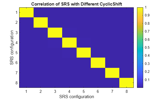
それぞれ異なる時間領域サイクリック シフトを使用して生成された SRS 波形間の相関が低いことは、それらの直交性を示しています。
disp('Absolute value of correlation matrix: '); disp(' '); disp(abs(srsCorr));
Absolute value of correlation matrix:

    1.0000    0.0027    0.0021    0.0008    0.0003    0.0010    0.0007    0.0038
    0.0027    1.0000    0.0030    0.0006    0.0006    0.0001    0.0006    0.0005
    0.0021    0.0030    1.0000    0.0041    0.0007    0.0008    0.0003    0.0008
    0.0008    0.0006    0.0041    1.0000    0.0040    0.0004    0.0009    0.0000
    0.0003    0.0006    0.0007    0.0040    1.0000    0.0039    0.0002    0.0009
    0.0010    0.0001    0.0008    0.0004    0.0039    1.0000    0.0039    0.0003
    0.0007    0.0006    0.0003    0.0009    0.0002    0.0039    1.0000    0.0039
    0.0038    0.0005    0.0008    0.0000    0.0009    0.0003    0.0039    1.0000
まとめとその他の調査
この例では、SRS シーケンスを生成して OFDM キャリア リソース グリッドにマッピングする方法と、複数キャリアと SRS の構成に対応する波形を生成する方法について説明します。この例では、SRS 構成パラメーターと、それらがリソース グリッドと SRS 波形プロパティの両方に与える影響との関係を強調します。以下に例を示します。
SRS に割り当てられる帯域幅は、通常、
CSRSが増えるにしたがって増加し、BSRSが増えるにしたがって減少します。周波数ホッピング構成の場合、瞬時帯域幅とホッピング帯域幅はそれぞれBSRSとBHopが増えるにしたがって減少します。SRS の周波数位置は、
FrequencyStartパラメーターとNRRCパラメーターによって決まります。NRRCは、異なる SRS サブバンドと周波数ホッピング パターンの選択を可能にします。BHop < BSRSでは一般に周波数ホッピングが生成されますが、それが保証されるわけではありません。しかし、BHop >= BSRSは、周波数ホッピングを無効にするのに十分です。スロット間周波数ホッピングは、リソース タイプが
periodicおよびsemi-persistentの場合にのみ有効です。時間、周波数、およびシーケンス関連のパラメーターを使用して、直交 SRS 送信を作成できます。
この例では、SRS 帯域幅構成テーブルと読み取り専用プロパティの両方から、NRRC によって構成可能な一意の SRS サブバンドの数や周波数ホッピング パターンなどの有用な情報を抽出する方法も示します。
マルチポート構成の SRS シーケンス生成では、サイクリックシフト直交 SRS で紹介されている直交化メカニズムが採用されています。複数のポート間の直交性を検証するには、マルチポート SRS を構成し、シンボルとインデックスを生成し、シンボルをリソース グリッドにマップし、SRS 波形を生成し、各ポートに対して生成された波形間の相互相関を計算します。
参考文献
[1] 3GPP TS 38.211. “NR; Physical channels and modulation.” 3rd Generation Partnership Project; Technical Specification Group Radio Access Network.
[2] 3GPP TS 38.331. “NR; Radio Resource Control (RRC) protocol specification.” 3rd Generation Partnership Project; Technical Specification Group Radio Access Network.
ローカル関数
この例では、次のローカル関数を使用します。
function [csrs,bsrs] = hSRSBandwidthConfiguration(srs, NRB)
% [CSRS,BSRS] = hBandwidthConfiguration(SRS, NRB) returns the SRS
% bandwidth configuration parameters CSRS and BSRS required to transmit an
% SRS in a bandwidth specified by NRB. The function calculates CSRS and
% BSRS considering the SRS properties FrequencyStart and NRRC, so the
% available bandwidth NRB is reduced by the frequency origin of the SRS.
% For frequency hopping cases, the value of BSRS returned is equal to that
% of the BSRS property in the input SRS configuration object.

    f0 = hSRSFrequencyOrigin(srs);
    NRB = NRB - f0;
    if NRB < 4
        error('The available bandwidth is not sufficient to allocate an SRS transmission. Increase the carrier bandwidth or configure the SRS in a lower frequency.' )
    end

    % For frequency hopping configurations
    if srs.BHop >= srs.BSRS && nargout == 2 % No frequency hopping and BSRS is requested
        BSRS = 0:3;
    else
        BSRS = 0;
    end

    % Initialize gap between SRS frequency allocation and carrier bandwidth
    NRBGap = NRB;

    % Find the appropriate CSRS for each BSRS that minimizes the gap only
    % in non-hopping cases. For freq. hopping, find the value of CSRS only.
    for b = BSRS
        % NRB allocated to the SRS for BSRS = b and all CSRS
        srsNRBb = srs.BandwidthConfigurationTable{:,2*(b+1)};
        mSRSbMax = max( srsNRBb( srsNRBb <= NRB ));

        % Calculate gap between SRS allocation and carrier bandwidth
        gap = NRB - mSRSbMax;
        if gap < NRBGap
            csrs = srs.BandwidthConfigurationTable{ srsNRBb == mSRSbMax ,1};
            bsrs = b;
            NRBGap = gap;
        end
    end
    csrs = csrs(1);

    if srs.BHop < bsrs
        bsrs = srs.BSRS;
    end
end

function out = hSRSNumberOfSubbandsOrHoppingPatterns(srs)
% N = hSRSNumberOfSubbandsOrHoppingPatterns(SRS) returns the number of
% unique SRS subbands or frequency-hopping patterns N configurable by the
% SRS property NRRC. An SRS subband is the frequency band allocated for SRS
% in a given OFDM symbol (See SRS property NRBPerTransmission). N is
% calculated using TS 38.211 Table 6.4.1.4.3-1 for the bandwidth
% configuration parameters CSRS, BSRS, and BHop specified in the SRS
% configuration object SRS.

    bwct = nrSRSConfig.BandwidthConfigurationTable{:,:};
    if srs.BHop < srs.BSRS % Number of unique frequency-hopping patterns
        b0 = srs.BHop+1;
    else % Number of unique SRS subbands
        b0 = 0;
    end
    out = prod(bwct(srs.CSRS+1,2*(b0:srs.BSRS)+3));
end

function [Grid,dispGrid] = hSRSGrid(carrier,srs,Duration,displayGrid,chplevels)
% [GRID,DISPGRID] = hSRSGrid(CARRIER,SRS,DURATION,DISPLAYGRID,CHPLEVELS)
% returns a multi-slot OFDM resource grid GRID containing a set of sounding
% reference signals in a carrier, as specified by the configuration objects
% CARRIER and SRS. This function also returns a scaled version of the grid
% used for display purposes. The optional input DURATION (Default 1)
% specifies the number of slots of the generated grid. The resource grid
% can be displayed using the optional input DISPLAYGRID (Default false).
% CHPLEVELS specifies the channel power levels for display purposes only
% and it must be of the same size as SRS.

    numSRS = length(srs);
    if nargin < 5
        chplevels = 1:-1/numSRS:1/numSRS;
        if nargin < 4
            displayGrid = false;
            if nargin < 3
                Duration = 1;
            end
        end
    end

    SymbolsPerSlot = carrier.SymbolsPerSlot;
    emptySlotGrid = nrResourceGrid(carrier,max([srs(:).NumSRSPorts])); % Initialize slot grid

    % Create the SRS symbols and indices and populate the grid with the SRS symbols
    Grid = repmat(emptySlotGrid,1,Duration);
    dispGrid = repmat(emptySlotGrid,1,Duration); % Frame-size grid for display
    for ns = 0:Duration-1
        slotGrid = emptySlotGrid;
        dispSlotGrid = emptySlotGrid; % Slot-size grid for display
        for ich = 1:numSRS
            srsIndices = nrSRSIndices(carrier,srs(ich));
            srsSymbols = nrSRS(carrier,srs(ich));
            slotGrid(srsIndices) = srsSymbols;
            dispSlotGrid(srsIndices) = chplevels(ich)*srsSymbols; % Scale the SRS for display only
        end
        OFDMSymIdx = ns*SymbolsPerSlot + (1:SymbolsPerSlot);
        Grid(:,OFDMSymIdx,:) = slotGrid;
        dispGrid(:,OFDMSymIdx,:) = dispSlotGrid;
        carrier.NSlot = carrier.NSlot+1;
    end

    if displayGrid
        plotGrid(dispGrid(:,:,1),chplevels,"SRS " + (1:numSRS)');
    end
end

function varargout = plotGrid(Grid,chplevels,leg)
% plotGrid(GRID, CHPLEVEL,LEG) displays a resource grid GRID containing
% channels or signals at different power levels CHPLEVEL and create a
% legend for these using a cell array of character vector LEG

    if nargin < 3
        leg = {'SRS'};
        if nargin < 2
            chplevels = 1;
        end
    end

    cmap = colormap(gcf);
    chpscale = length(cmap); % Scaling factor

    h = figure;
    image(0:size(Grid,2)-1,(0:size(Grid,1)-1)/12,chpscale*abs(Grid(:,:,1))); % Multiplied with scaling factor for better visualization
    axis xy;

    title('Carrier Grid Containing SRS')
    xlabel('OFDM Symbol'); ylabel('RB');

    clevels = chpscale*chplevels(:);
    N = length(clevels);
    L = line(ones(N),ones(N),'LineWidth',8); % Generate lines

    % Index the color map and associate the selected colors with the lines
    set(L,{'color'},mat2cell(cmap( min(1+fix(clevels),length(cmap) ),:),ones(1,N),3)); % Set the colors according to cmap

    % Create legend
    legend(leg(:));

    if nargout > 0
        varargout = {h};
    end
end

function hSRSAnnotations(carrier,srs)
% hSRSAnnotations(carrier,srs) adds annotation to the current figure
% indicating the frequency origin of the SRS and the number of RB used per
% OFDM symbol for the configuration objects CARRIER and SRS.

    % Calculate the frequency origin of the first SRS symbol
    f0 = hSRSFrequencyOrigin(srs);

    hold on;
    hfig = gcf;
    set(hfig,'Units','Normalized');
    Sym0 = srs.SymbolStart-0.5;
    if isnumeric(srs.SRSPeriod)
        Sym0 = srs.SRSPeriod(2)*carrier.SymbolsPerSlot + srs.SymbolStart-0.5;
    end

    IP = get(gca,'Position');

    % Y-coordinate in the current axes of the SRS freq position f0
    Yf0 = f0/carrier.NSizeGrid*IP(4)+IP(2);
    Xc = Sym0/((carrier.NSlot+1)*carrier.SymbolsPerSlot)*IP(3)+IP(1);

    % Add annotation to the figure including f0 in RB
    if f0/carrier.NSizeGrid > 0.08 % Only plot f0 when there is enough space in the y-axis
        % Create doublearrow for F0
        YMin = IP(2);
        annotation(hfig,'doublearrow',Xc*[1 1], [YMin Yf0],...
            'Color',[1 0.4 0.15]);

        % Text for F0
        str = sprintf('$$F_0 = %d $$ RB', f0);
        Ystr = f0/carrier.NSizeGrid/2;
        text(gca,(Xc-IP(1))/IP(3)-0.25, Ystr,str,...
            'Color',[1 0.4 0.15],'FontSize',14, ...
            'Units','Normalized','Interpreter','latex');
    end

    % Create doublearrow from f0 and spanning the SRS bandwidth
    Yf1 = Yf0 + srs.NRBPerTransmission/carrier.NSizeGrid*IP(4);
    annotation(hfig,'doublearrow',Xc*[1 1], [Yf0 Yf1],...
        'Color',[1 0.4 0.15]);

    % Text for NRBt
    str = sprintf('$$\\textrm{NRB}_T = %d $$ RB', srs.NRBPerTransmission);
    Ystr = (f0 + 0.5*srs.NRBPerTransmission)/carrier.NSizeGrid;
    text(gca,(Xc-IP(1))/IP(3)-0.32, Ystr ,str,...
        'Color',[1 0.4 0.15],'FontSize',14, ...
        'Units','Normalized','Interpreter','latex');
end

function f0 = hSRSFrequencyOrigin(srs)
% Calculate the frequency origin of the first SRS symbol in a slot

    NSBTable = hSRSNumberOfSubbandsOrHoppingPatterns(srs);
    NRBt = srs.NRBPerTransmission;

    % Origin of the SRS in frequency in RB
    f0 = srs.FrequencyStart + NRBt*mod(floor(4*srs.NRRC/NRBt),NSBTable);
end

function [NRRC,NRB] = hNRRCSet(srs)
% Calculate the values of NRRC that generate a unique set of orthogonal SRS in frequency
    if srs.BHop < srs.BSRS % Frequency-hopping cases
        NRB = srs(1).NRB;  % Hopping bandwidth
    else
        NRB = nrSRSConfig.BandwidthConfigurationTable{srs(1).CSRS+1,2};
    end

    % Number of frequency-hopping patterns or SRS subbands depending on the values of BSRS and BHop
    N = hSRSNumberOfSubbandsOrHoppingPatterns(srs);

    NRRC = NRB/4*(0:N-1)/N;
end
参照
[1] 3GPP TS 38.211. “NR; Physical channels and modulation.” 3rd Generation Partnership Project; Technical Specification Group Radio Access Network.