CSI-RS を使用した NR ダウンリンク送信側のビーム調整
この例では、5G Toolbox™ のチャネル状態情報基準信号 (CSI-RS) を使用したダウンリンク送信側のビーム調整手続きを示します。この例では、散乱環境において複数の CSI-RS リソースをさまざまな方向に送信する方法と、基準信号受信電力 (RSRP) 測定値に基づいて最適な送信ビームを選択する方法を示します。
はじめに
NR 5G の周波数範囲 2 (FR2) は、ミリメートル波 (mmWave) の周波数 (24.25 GHz ~ 52.6 GHz) で運用されます。周波数が高くなるにつれて送信信号のパス損失と侵入損失が高くなる傾向があり、これによりリンク バジェットが影響を受けます。高い周波数で信号を送受信する際のゲインと指向性を改善するには、ビームフォーミングを行う必要があります。ビーム管理は、良好な接続を実現する最適なビーム ペア (送信ビームおよび対応する受信ビーム) を確立して保持するための、レイヤー 1 (物理レイヤー) とレイヤー 2 (メディア アクセス制御) の手順のセットです。TR 38.802 の Section 6.1.6.1 [1] では、ビームの管理が 3 つの手続きとして定義されています。
手続き 1 (P-1): この手続きは、同期信号ブロック (SSB) に基づく初期捕捉に焦点を当てています。初期捕捉の際に、送信側と受信側の両方でビーム スイーピングを行い、RSRP 測定値に基づいて最適なビーム ペアを選択します。一般に、選択されたビームは幅が広く、データの送受信にとって最適なビーム ペアではない可能性があります。この手続きの詳細については、NR SSB のビーム スイーピングを参照してください。
手続き 2 (P-2): この手続きは、送信側のビーム調整に焦点を当てています。ここでは、受信ビームを固定したまま送信側でビーム スイーピングを行います。この手続きは、ダウンリンク送信側のビーム調整については非ゼロ電力 CSI-RS (NZP-CSI-RS) に基づいて行い、アップリンク送信側のビーム調整についてはサウンディング基準信号 (SRS) に基づいて行います。
初期捕捉後に指向性とゲインの高いユニキャスト データ伝送を行うには、SSB ビームよりも細いビームが必要となります。そのため、一連の基準信号リソースを構成し、初期捕捉処理で得られたビーム角度範囲内でより細いビームを使用して、そのリソースをさまざまな方向に送信します。その後、ユーザー端末 (UE) またはアクセス ネットワーク ノード (gNB) において、固定された受信ビームを使って信号を取得し、それらのビームをすべて測定します。最後に、すべての送信ビームの RSRP 測定値に基づいて最適な送信ビームを選択します。
手続き 3 (P-3): この手続きは、受信側のビーム調整に焦点を当てています。ここでは、現在の送信ビームに対して受信側でビーム スイーピングを行います。この処理は、最適な受信ビームを見つけることを目的としています。これは、隣接するビームの場合もあれば、調整されたビームの場合もあります。この手続きでは、同じ送信ビームを使って一連の基準信号リソース (ダウンリンクの場合は NZP-CSI-RS、アップリンクの場合は SRS) を送信し、一定の角度範囲をカバーするさまざまな方向のさまざまなビームを使用して UE または gNB でその信号を受信します。最後に、すべての受信ビームの RSRP 測定値に基づいて最適な受信ビームを選択します。
この例は、送信機におけるダウンリンクのビーム調整に焦点を当てています。この例は、NR 5G の周波数範囲 1 (FR1) と周波数範囲 2 (FR2) のどちらでも機能します。次の図では、4 つの NZP-CSI-RS リソースを 4 つの異なる方向に送信する場合の送信側のビーム調整手続きを示しています。

この図では、この例の主な処理手順を示しており、送信側のビーム調整手続きに関連する手順を色分けして示しています。

CSI-RS リソースの生成
キャリアの構成
30 kHz のサブキャリア間隔で 50 MHz のキャリアを表すキャリア構成オブジェクトを作成します。
carrier = nrCarrierConfig;
% Maximum transmission bandwidth configuration for 50 MHz carrier with 30 kHz subcarrier spacing
carrier.NSizeGrid = 133;
carrier.SubcarrierSpacing = 30;
carrier.NSlot = 0;
carrier.NFrame = 0
carrier =
nrCarrierConfig with properties:
NCellID: 1
SubcarrierSpacing: 30
CyclicPrefix: 'normal'
NSizeGrid: 133
NStartGrid: 0
NSlot: 0
NFrame: 0
IntraCellGuardBands: [0×2 double]
Read-only properties:
SymbolsPerSlot: 14
SlotsPerSubframe: 2
SlotsPerFrame: 20
CSI-RS の構成
numNZPRes 個の NZP-CSI-RS リソースから成る NZP-CSI-RS リソース セットを表す CSI-RS 構成オブジェクトを作成します。レイヤー 1 の RSRP 測定用に、TS 38.215 の Section 5.1.2 [2] または TS 38.214 の Section 5.1.6.1.2 [3] の規定に従い、同じ数のアンテナ ポート (シングルポートまたはデュアルポート) を使って 1 つのリソース セットにすべての CSI-RS リソースを構成します。この例は、シングルポートの CSI-RS で機能します。
numNZPRes = 12;
csirs = nrCSIRSConfig;
csirs.CSIRSType = repmat({'nzp'},1,numNZPRes);
csirs.CSIRSPeriod = 'on';
csirs.Density = repmat({'one'},1,numNZPRes);
csirs.RowNumber = repmat(2,1,numNZPRes);
csirs.SymbolLocations = {0,1,2,3,4,5,6,7,8,9,10,11};
csirs.SubcarrierLocations = repmat({0},1,numNZPRes);
csirs.NumRB = 25
csirs =
nrCSIRSConfig with properties:
CSIRSType: {'nzp' 'nzp' 'nzp' 'nzp' 'nzp' 'nzp' 'nzp' 'nzp' 'nzp' 'nzp' 'nzp' 'nzp'}
CSIRSPeriod: 'on'
RowNumber: [2 2 2 2 2 2 2 2 2 2 2 2]
Density: {'one' 'one' 'one' 'one' 'one' 'one' 'one' 'one' 'one' 'one' 'one' 'one'}
SymbolLocations: {[0] [1] [2] [3] [4] [5] [6] [7] [8] [9] [10] [11]}
SubcarrierLocations: {[0] [0] [0] [0] [0] [0] [0] [0] [0] [0] [0] [0]}
NumRB: 25
RBOffset: 0
NID: 0
Read-only properties:
NumCSIRSPorts: [1 1 1 1 1 1 1 1 1 1 1 1]
CDMType: {'noCDM' 'noCDM' 'noCDM' 'noCDM' 'noCDM' 'noCDM' 'noCDM' 'noCDM' 'noCDM' 'noCDM' 'noCDM' 'noCDM'}
% Validate CSI-RS antenna ports
validateCSIRSPorts(csirs);

% Get the binary vector to represent the presence of each CSI-RS resource
% in a specified slot
csirsTransmitted = getActiveCSIRSRes(carrier,csirs);
すべての NZP-CSI-RS リソースのパワー スケーリングをデシベル (dB) 単位で構成します。
powerCSIRS = 0;
CSI-RS シンボルとインデックスの生成
構成オブジェクト carrier および csirs を使用し、CSI-RS のシンボルとインデックスを生成します。各 CSI-RS リソースの出力を個別に識別するには、名前と値のペア OutputResourceFormat,'cell' を指定します。
csirsSym = nrCSIRS(carrier,csirs,'OutputResourceFormat','cell')
csirsSym=1×12 cell array
    {25×1 double}    {25×1 double}    {25×1 double}    {25×1 double}    {25×1 double}    {25×1 double}    {25×1 double}    {25×1 double}    {25×1 double}    {25×1 double}    {25×1 double}    {25×1 double}
csirsInd = nrCSIRSIndices(carrier,csirs,'OutputResourceFormat','cell')
csirsInd=1×12 cell array
    {25×1 uint32}    {25×1 uint32}    {25×1 uint32}    {25×1 uint32}    {25×1 uint32}    {25×1 uint32}    {25×1 uint32}    {25×1 uint32}    {25×1 uint32}    {25×1 uint32}    {25×1 uint32}    {25×1 uint32}
アンテナ アレイと散乱体の構成
送信側および受信側のアンテナ アレイの構成
搬送波周波数と信号伝播速度を構成します。
% Set the carrier frequency
fc = 3.5e9;
freqRange = validateFc(fc);

% Set the propagation speed
c = physconst('LightSpeed');
% Calculate wavelength
lambda = c/fc;
送信側と受信側のアンテナ アレイのサイズを 2 要素ベクトルとして構成します。ここで、最初の要素はアンテナ アレイの行数を表し、2 番目の要素はアンテナ アレイの列数を表します。
txArySize = [8 8];
rxArySize = [2 2];
送信アンテナ素子と受信アンテナ素子の総数を計算します。
nTx = prod(txArySize);
nRx = prod(rxArySize);
送信側と受信側のアンテナ アレイの位置を構成します。次に、送信側と受信側のアンテナ アレイ位置間の空間間隔に基づき、自由空間パス損失を計算します。
% Configure antenna array positions
txArrayPos = [0;0;0];
rxArrayPos = [100;50;0];

% Calculate the free space path loss
toRxRange = rangeangle(txArrayPos,rxArrayPos);
spLoss = fspl(toRxRange,lambda);
アンテナ アレイのサイズに基づき、等間隔直線アレイ (ULA) または等間隔矩形アレイ (URA) を構成します。
% Initialize the flags to choose between URA and ULA
isTxRectArray = false;
isRxRectArray = false;

% Enable isTxRectArray if both the number of rows and columns of transmit
% antenna array are greater than one
if ~any(txArySize == 1)
    isTxRectArray = true;
end
% Enable isRxRectArray if both the number of rows and columns of receive
% antenna array are greater than one
if ~any(rxArySize == 1)
    isRxRectArray = true;
end

% Configure the transmit and receive antenna elements
txAntenna = phased.IsotropicAntennaElement('BackBaffled',true);  % To avoid transmission beyond +/- 90
                                                                 % degrees from the broadside, baffle
                                                                 % the back of the transmit antenna
                                                                 % element by setting the BackBaffled
                                                                 % property to true
rxAntenna = phased.IsotropicAntennaElement('BackBaffled',false); % To receive the signal from 360 degrees,
                                                                 % set the BackBaffled property to false

% Configure transmit antenna array
if isTxRectArray
    % Create a URA System object for signal transmission
    txArray = phased.URA('Element',txAntenna,'Size',txArySize,'ElementSpacing',lambda/2);
else
    % Create a ULA System object for signal transmission
    txArray = phased.ULA('Element',txAntenna,'NumElements',nTx,'ElementSpacing',lambda/2);
end

% Configure receive antenna array
if isRxRectArray
    % Create a URA System object for signal reception
    rxArray = phased.URA('Element',rxAntenna,'Size',rxArySize,'ElementSpacing',lambda/2);
else
    % Create a ULA System object for signal reception
    rxArray = phased.ULA('Element',rxAntenna,'NumElements',nRx,'ElementSpacing',lambda/2);
end
散乱体の構成
fixedScatMode = true;
rng(42);
if fixedScatMode
    % Fixed single scatterer location
    numScat = 1;
    scatPos = [60;10;15];
else
    % Generate scatterers at random positions
    numScat = 10; %#ok<UNRCH>
    azRange = -180:180;
    randAzOrder = randperm(length(azRange));
    elRange = -90:90;
    randElOrder = randperm(length(elRange));
    azAngInSph = deg2rad(azRange(randAzOrder(1:numScat)));
    elAngInSph = deg2rad(elRange(randElOrder(1:numScat)));
    r = 20;

    % Transform spherical coordinates to Cartesian coordinates
    [x,y,z] = sph2cart(azAngInSph,elAngInSph,r);
    scatPos = [x;y;z] + (txArrayPos + rxArrayPos)/2;
end
送信ビームフォーミングと OFDM 変調
ステアリング ベクトルの計算
送信アンテナ アレイの steering vector System object™ を作成します。
txArrayStv = phased.SteeringVector('SensorArray',txArray,'PropagationSpeed',c);
送信アンテナ アレイを基準とした散乱体位置の角度を計算します。
[~,scatAng] = rangeangle(scatPos(:,1),txArrayPos); % Pointing towards the first scatterer position, in case of multiple scatterers初期捕捉処理 (P-1) で得られた SSB 送信ビームの方位角面と仰角面のビーム幅を構成します。
azTxBeamWidth = 30; % In degrees
elTxBeamWidth = 30; % In degrees
方位角面と仰角面のビーム幅を使用し、散乱体の位置と (部分的または完全に) 向きが等しい SSB 送信ビーム方向を取得します。
ssbTxAng = getInitialBeamDir(scatAng,azTxBeamWidth,elTxBeamWidth);
SSB 送信ビームがカバーする角度範囲内で、アクティブなすべての CSI-RS リソースのビーム方向 (方位角と仰角のペア) を計算します。
% Get the number of transmit beams based on the number of active CSI-RS resources in a slot
numBeams = sum(csirsTransmitted);

% Get the azimuthal sweep range based on the SSB transmit beam direction
% and its beamwidth in azimuth plane
azSweepRange = [ssbTxAng(1) - azTxBeamWidth/2 ssbTxAng(1) + azTxBeamWidth/2];

% Get the elevation sweep range based on the SSB transmit beam direction
% and its beamwidth in elevation plane
elSweepRange = [ssbTxAng(2) - elTxBeamWidth/2 ssbTxAng(2) + elTxBeamWidth/2];

% Get the azimuth and elevation angle pairs for all NZP-CSI-RS transmit beams
azBW = beamwidth(txArray,fc,'Cut','Azimuth');
elBW = beamwidth(txArray,fc,'Cut','Elevation');
csirsBeamAng = hGetBeamSweepAngles(numBeams,azSweepRange,elSweepRange,azBW,elBW);
アクティブなすべての CSI-RS リソースについて、ステアリング ベクトルを計算します。
wT = zeros(nTx,numBeams);
for beamIdx = 1:numBeams
    tempW = txArrayStv(fc,csirsBeamAng(:,beamIdx));
    wT(:,beamIdx) = tempW;
end
デジタル ビームフォーミングの適用
すべての NZP-CSI-RS リソースをループ処理し、アクティブなリソースすべてにデジタル ビームフォーミングを適用します。デジタル ビームフォーミングは、同じ OFDM シンボル内で周波数選択性ビームフォーミングを提供できると考えられています。
% Number of CSI-RS antenna ports
ports = csirs.NumCSIRSPorts(1);
% Initialize the beamformed grid
bfGrid = nrResourceGrid(carrier,nTx);
% Get the active NZP-CSI-RS resource indices
activeRes = find(logical(csirsTransmitted));
for resIdx = 1:numNZPRes
    % Initialize the carrier resource grid for one slot and map NZP-CSI-RS symbols onto
    % the grid
    txSlotGrid = nrResourceGrid(carrier,ports);
    txSlotGrid(csirsInd{resIdx}) = db2mag(powerCSIRS)*csirsSym{resIdx};
    reshapedSymb = reshape(txSlotGrid,[],ports);

    % Get the transmit beam index
    beamIdx = find(activeRes == resIdx);

    % Apply the digital beamforming
    if ~isempty(beamIdx)
        bfSymb = reshapedSymb * wT(:,beamIdx)';
        bfGrid = bfGrid + reshape(bfSymb,size(bfGrid));
    end
end
OFDM 変調の実行
OFDM 変調を実行し、時間領域の波形を生成します。
% Perform OFDM modulation
[tbfWaveform,ofdmInfo] = nrOFDMModulate(carrier,bfGrid);

% Normalize the beamformed time-domain waveform over the number of transmit
% antennas
tbfWaveform = tbfWaveform/sqrt(nTx);
散乱 MIMO チャネルと AWGN
チャネルの構成
System objectphased.ScatteringMIMOChannel (Phased Array System Toolbox) を使用し、散乱に基づく MIMO 伝播チャネルを構成します。このチャネル モデルは、時間遅延、ゲイン、ドップラー シフト、位相変化、自由空間パス損失、およびオプションでその他の大気減衰を入力に適用します。
chan = phased.ScatteringMIMOChannel;
chan.PropagationSpeed = c;
chan.CarrierFrequency = fc;
chan.Polarization = 'none';
chan.SpecifyAtmosphere = false;
chan.SampleRate = ofdmInfo.SampleRate;
chan.SimulateDirectPath = false;
chan.ChannelResponseOutputPort = true;

% Configure transmit array parameters
chan.TransmitArray = txArray;
chan.TransmitArrayMotionSource = 'property';
chan.TransmitArrayPosition = txArrayPos;

% Configure receive array parameters
chan.ReceiveArray = rxArray;
chan.ReceiveArrayMotionSource = 'property';
chan.ReceiveArrayPosition = rxArrayPos;

% Configure scatterers
chan.ScattererSpecificationSource = 'property';
chan.ScattererPosition = scatPos;
chan.ScattererCoefficient = ones(1,numScat);

% Get the maximum channel delay by transmitting random signal
[~,~,tau] = chan(complex(randn(chan.SampleRate*1e-3,nTx), ...
    randn(chan.SampleRate*1e-3,nTx)));
maxChDelay = ceil(max(tau)*chan.SampleRate);
チャネルを使用した波形の送信
チャネルの内容をフラッシュするために送信波形の末尾にゼロを追加してから、時間領域波形を散乱 MIMO チャネルに渡します。これらのゼロは、チャネルで発生する遅延を想定しています。
% Append zeros to the transmit waveform to account for channel delay
tbfWaveform = [tbfWaveform; zeros(maxChDelay,nTx)];
% Pass the waveform through the channel
fadWave = chan(tbfWaveform);
AWGN の適用
受信ゲインを構成して劣化した波形に適用し、パス損失を補正します。次に、結果として得られた波形に AWGN を適用します。この例で使用している SNR 定義の説明については、リンク シミュレーションで使用する SNR の定義を参照してください。
% Configure the receive gain
rxGain = 10.^((spLoss)/20); % Gain in linear scale
% Apply the gain
fadWaveG = fadWave*rxGain;

% Configure the SNR in dB
SNRdB = 20;
SNR = 10^(SNRdB/10); % SNR in linear scale
% Calculate the standard deviation for AWGN
N0 = 1/sqrt(2.0*nRx*double(ofdmInfo.Nfft)*SNR);

% Generate AWGN
noise = N0*complex(randn(size(fadWaveG)),randn(size(fadWaveG)));
% Apply AWGN to the waveform
rxWaveform = fadWaveG + noise;
タイミング同期
受信した基準シンボルと NZP-CSI-RS シンボルのローカル コピーとの相互相関を求め、タイミング同期を実行します。
% Generate reference symbols and indices
refSym = nrCSIRS(carrier,csirs);
refInd = nrCSIRSIndices(carrier,csirs);

% Estimate timing offset
offset = nrTimingEstimate(carrier,rxWaveform,refInd,refSym);
if offset > maxChDelay
    offset = 0;
end

% Correct timing offset
syncTdWaveform = rxWaveform(1+offset:end,:);
OFDM 復調と受信ビームフォーミング
OFDM 復調
同期した時間領域波形を OFDM 復調します。
rxGrid = nrOFDMDemodulate(carrier,syncTdWaveform);
ステアリング ベクトルの計算
受信アンテナ アレイの steering vector System object を作成します。
rxArrayStv = phased.SteeringVector('SensorArray',rxArray,'PropagationSpeed',c);
受信アンテナ アレイを基準とした散乱体位置の角度を計算します。これを、SSB を使用した初期捕捉処理で得られた受信ビームの方向とします。
[~,scatRxAng] = rangeangle(scatPos(:,1),rxArrayPos); % Pointing towards the first scatterer position, in case of multiple scatterers初期捕捉処理 (P-1) で得られた受信ビームの方位角面と仰角面のビーム幅を構成します。
azRxBeamWidth = 30; % In degrees
elRxBeamWidth = 30; % In degrees
P-1 で得られた方位角面と仰角面のビーム幅を使用し、散乱体位置と (部分的または完全に) 向きが等しい初期受信ビーム方向を取得します。
rxAng = getInitialBeamDir(scatRxAng,azRxBeamWidth,elRxBeamWidth);
受信角度に関するステアリング ベクトルを計算します。
wR = rxArrayStv(fc,rxAng);
受信ビームフォーミングの適用
受信側でデジタル ビームフォーミングを実行するには、rxGrid に他の信号が存在しないと仮定して (単一 UE のシナリオ)、ステアリングの重みを rxGrid に適用します。FR2 の場合は、TS 38.215 の Section 5.1.2 [2] で規定されているように、すべての受信アンテナ素子からの信号を結合します。
temp = rxGrid;
if strcmpi(freqRange,'FR1')
    % Beamforming without combining
    rbfGrid = reshape(reshape(temp,[],nRx).*wR',size(temp,1),size(temp,2),[]);
else % 'FR2'
    % Beamforming with combining
    rbfGrid = reshape(reshape(temp,[],nRx)*conj(wR),size(temp,1),size(temp,2),[]);
end
散乱 MIMO のシナリオのプロット
MIMO のシーン パラメーターを構成します。
sceneParams.TxArray = txArray;
sceneParams.RxArray = rxArray;
sceneParams.TxArrayPos = txArrayPos;
sceneParams.RxArrayPos = rxArrayPos;
sceneParams.ScatterersPos = scatPos;
sceneParams.Lambda = lambda;
sceneParams.ArrayScaling = 100;   % To enlarge antenna arrays in the plot
sceneParams.MaxTxBeamLength = 45; % Maximum length of transmit beams in the plot
sceneParams.MaxRxBeamLength = 25; % Maximum length of receive beam in the plot
補助関数 hPlotSpatialMIMOScene を使用し、散乱 MIMO のシナリオ (送信側と受信側のアンテナ アレイ、散乱体位置とそのパス、および送信側と受信側のアンテナ アレイのすべてのビーム パターン) をプロットします。この図のビーム パターンは、線形スケールの電力パターンと似ています。
hPlotSpatialMIMOScene(sceneParams,wT,wR);
axis tight;
view([74 29]);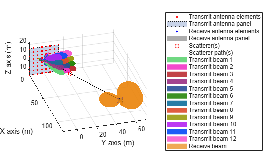
ビームの決定
UE は、OFDM 復調後、現在の受信ビームの条件で、さまざまなビームによって送信されたすべての CSI-RS リソースの RSRP を測定します。関数 nrCSIRSMeasurements を使用してこれらの測定を実行します。
% Perform RSRP measurements
meas = nrCSIRSMeasurements(carrier,csirs,rbfGrid);

% Display the measurement quantities for all CSI-RS resources in dBm
RSRPdBm = max(meas.RSRPPerAntenna,[],1);
disp(['RSRP measurements of all CSI-RS resources (in dBm):' 13 num2str(RSRPdBm)]);
RSRP measurements of all CSI-RS resources (in dBm):
42.3147       33.237      29.1999      45.1102      37.0922      31.4861      39.9414      33.5053      24.5859      17.5821      12.9908      -1.9296
測定値から RSRP の最大値を特定し、それに対応する最適なビームを見つけます。
% Get the transmit beam index with maximum RSRP value
[~,maxRSRPIdx] = max(RSRPdBm(logical(csirsTransmitted)));

% Get the CSI-RS resource index with maximum RSRP value
[~,maxRSRPResIdx] = max(RSRPdBm);
調整後の送信ビームに対応するビーム幅を計算します。
% Get the steering weights corresponding to refined transmit beam
if numBeams == 0
    disp('Refinement has not happened, as NZP-CSI-RS is not transmitted')
else
    refBeamWts = wT(:,maxRSRPIdx);
    csirsAzBeamWidth = beamwidth(txArray,fc,'PropagationSpeed',c,'Weights',refBeamWts,'CutAngle',csirsBeamAng(2,maxRSRPIdx));
    csirsElBeamWidth = beamwidth(txArray,fc,'PropagationSpeed',c,'Weights',refBeamWts,'Cut','Elevation','CutAngle',csirsBeamAng(1,maxRSRPIdx));
    disp(['From initial beam acquisition:' 13 '    Beamwidth of initial SSB beam in azimuth plane is: '...
        num2str(azTxBeamWidth) ' degrees' 13 ...
        '    Beamwidth of initial SSB beam in elevation plane is: '...
        num2str(elTxBeamWidth) ' degrees' 13 13 ...
        'With transmit-end beam refinement:' 13 '    Refined transmit beam ('...
        num2str(maxRSRPIdx) ') corresponds to CSI-RS resource '...
        num2str(maxRSRPResIdx) ' is selected in the direction ['...
        num2str(csirsBeamAng(1,maxRSRPIdx)) ';' num2str(csirsBeamAng(2,maxRSRPIdx))...
        ']' 13 '    Beamwidth of refined transmit beam in azimuth plane is: '...
        num2str(csirsAzBeamWidth) ' degrees' 13 ...
        '    Beamwidth of refined transmit beam in elevation plane is: '...
        num2str(csirsElBeamWidth) ' degrees']);
end
From initial beam acquisition:
    Beamwidth of initial SSB beam in azimuth plane is: 30 degrees
    Beamwidth of initial SSB beam in elevation plane is: 30 degrees

With transmit-end beam refinement:
    Refined transmit beam (4) corresponds to CSI-RS resource 4 is selected in the direction [10;15]
    Beamwidth of refined transmit beam in azimuth plane is: 13.46 degrees
    Beamwidth of refined transmit beam in elevation plane is: 13.24 degrees
まとめとその他の調査
この例では、NZP-CSI-RS を使用したビーム調整手続き (P-2) について説明しています。この手続きでは、初期捕捉で得られたビームよりも細い送信ビームを特定します。
複数の CSI-RS リソース、送信側と受信側のアンテナ アレイ構成、および複数の散乱体を構成し、さまざまなビームの中から調整されたビームを選択することができます。また、信号を送受信する方位角と仰角のペアを構成することもできます。
参考文献
3GPP TR 38.802. "Study on New Radio access technology physical layer aspects." 3rd Generation Partnership Project; Technical Specification Group Radio Access Network.
3GPP TS 38.215. "NR; Physical layer measurements." 3rd Generation Partnership Project; Technical Specification Group Radio Access Network.
3GPP TS 38.214. "NR; Physical layer procedures for data." 3rd Generation Partnership Project; Technical Specification Group Radio Access Network.
ローカル関数
function validateCSIRSPorts(csirs)
%   validateCSIRSPorts validates the CSI-RS antenna ports, given the
%   CSI-RS configuration object CSIRS.

    numPorts = csirs.NumCSIRSPorts;
    if any(numPorts > 1)
        error('nr5g:PortsGreaterThan1','CSI-RS resources must be configured for single-port for RSRP measurements.');
    end
end

function csirsTransmitted = getActiveCSIRSRes(carrier,csirs)
%   getActiveCSIRSRes returns a binary vector indicating the presence of
%   all CSI-RS resources in a specified slot, given the carrier
%   configuration object CARRIER and CSI-RS configuration object CSIRS.

    % Extract the following properties of carrier
    NSlotA        = carrier.NSlot;          % Absolute slot number
    NFrameA       = carrier.NFrame;         % Absolute frame number
    SlotsPerFrame = carrier.SlotsPerFrame;  % Number of slots per frame

    % Calculate the appropriate frame number (0...1023) based on the
    % absolute slot number
    NFrameR = mod(NFrameA + fix(NSlotA/SlotsPerFrame),1024);
    % Relative slot number (0...slotsPerFrame-1)
    NSlotR = mod(NSlotA,SlotsPerFrame);

    % Loop over the number of CSI-RS resources
    numCSIRSRes = numel(csirs.CSIRSType);
    csirsTransmitted = zeros(1,numCSIRSRes);
    csirs_struct = validateConfig(csirs);
    for resIdx = 1:numCSIRSRes
        % Extract the CSI-RS slot periodicity and offset
        if isnumeric(csirs_struct.CSIRSPeriod{resIdx})
            Tcsi_rs = csirs_struct.CSIRSPeriod{resIdx}(1);
            Toffset = csirs_struct.CSIRSPeriod{resIdx}(2);
        else
            if strcmpi(csirs_struct.CSIRSPeriod{resIdx},'on')
                Tcsi_rs = 1;
            else
                Tcsi_rs = 0;
            end
            Toffset = 0;
        end

        % Check for the presence of CSI-RS, based on slot periodicity and offset
        if (Tcsi_rs ~= 0) && (mod(SlotsPerFrame*NFrameR + NSlotR - Toffset, Tcsi_rs) == 0)
            csirsTransmitted(resIdx) = 1;
        end
    end
end

function freqRange = validateFc(fc)
%   validateFc validates the carrier frequency FC and returns the frequency
%   range as either 'FR1' or 'FR2'.

    if fc >= 410e6 && fc <= 7.125e9
        freqRange = 'FR1';
    elseif fc >= 24.25e9 && fc <= 52.6e9
        freqRange = 'FR2';
    else
        error('nr5g:invalidFreq',['Selected carrier frequency is outside '...
            'FR1 (410 MHz to 7.125 GHz) and FR2 (24.25 GHz to 52.6 GHz).']);
    end
end

function beamDir = getInitialBeamDir(scatAng,azBeamWidth,elBeamWidth)
%   getInitialBeamDir returns the initial beam direction BEAMDIR, given the
%   angle of scatterer position with respect to transmit or receive antenna
%   array SCATANG, beamwidth of transmit or receive beam in azimuth plane
%   AZBEAMWIDTH, and beamwidth of transmit or receive beam in elevation
%   plane ELBEAMWIDTH.

    % Azimuth angle boundaries of all transmit/receive beams
    azSSBSweep = -180:azBeamWidth:180;
    % Elevation angle boundaries of all transmit/receive beams
    elSSBSweep = -90:elBeamWidth:90;

    % Get the azimuth angle of transmit/receive beam
    azIdx1 = find(azSSBSweep <= scatAng(1),1,'last');
    azIdx2 = find(azSSBSweep >= scatAng(1),1,'first');
    azAng = (azSSBSweep(azIdx1) + azSSBSweep(azIdx2))/2;

    % Get the elevation angle of transmit/receive beam
    elIdx1 = find(elSSBSweep <= scatAng(2),1,'last');
    elIdx2 = find(elSSBSweep >= scatAng(2),1,'first');
    elAng = (elSSBSweep(elIdx1) + elSSBSweep(elIdx2))/2;

    % Form the azimuth and elevation angle pair (in the form of [az;el])
    % for transmit/receive beam
    beamDir = [azAng;elAng];
end