結果:
Hi, currently I'm studying about DC-DC Boost converter with controller. After I applied the step time, the output voltage supposed to follow the step time, but there is some delay in the simulation results after I applied the "step time" in the step input block. Can someone help, why this delay occur? Please see the attached pictures. Thanks
MathWorks is please to offer a new training course, Power Electronics Control Design with Simulink and Simscape.
This one-day course focuses on modeling and controlling power electronic systems in the Simulink® environment using Simscape Electrical™. Topics include:
- Modeling direct current (dc) power electronic components
- Controlling the level of fidelity in a model
- Developing controls for power electronics
- Modeling three-phase alternating current (ac) power electronic components
- Controlling power electronics for motor drive applications
Hi everyone,
I am a third year BEng Energy Engineering student. I am looking at the design, modelling and peformance of an HVDC power converter for use in offshore wind for my final year dissertation. Power electronics is a new area for me and I am also new to simulink/ simscape elctrical.
Could anyone provide some useful examples of MMC (in particular rectifiers), or some advice for designing in simscape electrical. I am struggling with the design of PWM control especially. I aim to make a scaled down version of the MMC in Simulink but so far have had no luck. If anyone can help I would be really appreciative.
Thanks in advance.
Joe
Hi Everyone,
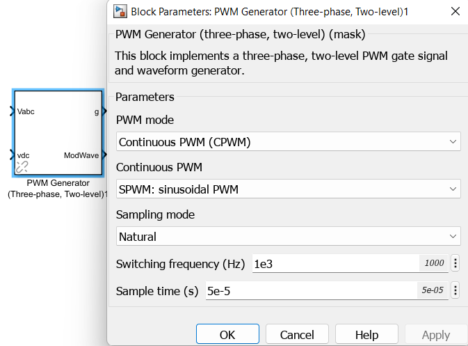
Require some guidance and pointers on model ee_pmlsm_drive please.

Its regarding a PMSM linear machine model, with a cascade (position and speed) outer loop and a current controller inner loop (Id and Iq currents).
The current Simulink model uses a low voltage DC supply (48v) and uses a step input to the system. My system uses a HV source (400v) and the input is sinusoidal position, with an operating frequency range of 0 to 20hz.
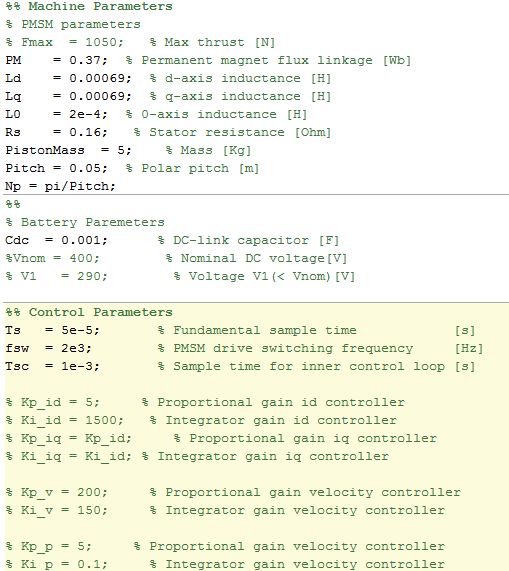
I have used the original model, re-created my own (to learn Simulink/Simscape) with a HV battery source (400v) and used machine parameters that match the application (peer reviewed publication).
As my power electronics background is limited, my background is mechanical, i am unable to tune the inner and outer loops, and am unsure in what order to tune. My project is to use the linear PMSM to drive (motoring) a linear piston for combustion and also use the linear piston to drive the PMSM (generating).
Using the built in PID tuner for the outer speed and position loops i am encountering an error (plant cannot be linearised). I am using a simple 1 hz sine wave to simulate the reference position set-point. With all PID values set to default i have no dq currents, however i have idq ref from the outer velocity controller loop.
Any help with resources and guidance as to how to tune the loops for my updated parameters on this model would be great.
Hi, Currently modelling an reciprocating engine coupled to a linear PMSM motor/generator for my PhD. I have downloaded the "Model File Package for Motor Control Design Public Video" simulink model.
Is it possible to convert to rotational PMSM simscape plant model used for a linear PMSM model? As there are none in the library to just drag into the existing control model.
Any ideas i can represent a linear motor based on this existing control model?
My output from the machine needs to be linear position w.r.t, with a total stroke of approximately 100 mm. Can i convert the rotational constant speed input at port "W" to a sinusoidal velocity profile (such that it replicates the velocity profile of a linear machine)?
Any help would be great.
Thanks
I have issue with the design that i have downloaded from mathwork community. how to solve regarding this matter
Failed to load library 'powerlib_models' referenced by 'mcupqc/Subsystem/Voltage Measurement/model' Component:Simulink | Category:Model error Failed to load library 'powerlib_models' referenced by 'mcupqc/Three-Phase V-I Measurement/model' Component:Simulink | Category:Model error Failed to load library 'powerlib_models' referenced by 'mcupqc/Three-Phase V-I Measurement1/model' Component:Simulink | Category:Model error Failed to load library 'powerlib_models' referenced by 'mcupqc/Three-Phase V-I Measurement2/model' Component:Simulink | Category:Model error Failed to load library 'powerlib_models' referenced by 'mcupqc/Three-Phase V-I Measurement3/model' Component:Simulink | Category:Model error Failed to load library 'powerlib_models' referenced by 'mcupqc/Three-Phase V-I Measurement4/model' Component:Simulink | Category:Model error Failed to load library 'powerlib_models' referenced by 'mcupqc/Three-Phase V-I Measurement5/model' Component:Simulink | Category:Model error Failed to load library 'powerlib_models' referenced by 'mcupqc/Three-Phase V-I Measurement6/model' Component:Simulink | Category:Model error
Explore resources, ask questions, and discuss topics related to using Simulink to apply power electronics control to Electric Vehicles, Renewable Energy, Battery Systems, Power Conversion, and Motor Control. This is the 3rd MATLAB Central community, after Maker and SimBiology , and is moderated by Tony Lennon . Tony is the Power Electronics Marketing Manager at MathWorks.
Visit the community here . As always, let us know what you think by liking this post or commenting below.

I am trying to design the outer voltage loop of the inverter but i am unable to remove the 5,7th harmonics from the capacitor voltage as i am trying to supply nonlinear load. The file is in matlab2018b.
Model-Based Design speeds up developing embedded software for controllers in power electronics-based systems. Wherever you plan to use digital controls, you can use Model-Based Design to develop, test, and implement your algorithms. You can learn more about Model-Based Design in this white paper .
Lithium-ion batteries play an important role in the success of electric vehicles, energy storage, and a host of other devices and equipment in our daily lives. Read the announcement here.
Learn more about how MathWorks enables the use of Lithium-ion battery technology
Visit MathWorks at booth 218 during the IEEE Energy Conversion Congress and Exposition (ECCE) in Baltimore, Sept. 29 - Oct. 3. We will be partnering with Speedgoat to show real-time simulation solutions for power electronics control design. Also, join us for a panel session, The Role of Simulation Software for Power Electronics Control Design in Education, that will be held Thursday, Oct. 3.
Many microcontroller companies support motor control development using Simulink and Embedded Coder. Here are some interesting reads about some of them. Do you know others? Let us know with your reply.
The new generation of power semiconductors is making it's way into the mainstream. IEEE is hosting a webinar with Brij Singh of John Deere, who will talk about the application of SiC in an inverter for a commercial loader. You can read the abstract and register here.
Also, there is a ouTube video of a hybrid loader shown here Pretty cool.
Good day everyone,
I'm trying to simulate a single phase transformator by using Simulink. I've got the current values: R1 = 3 Ohm R2 = 0.03 Ohm X1 = 6.5 Ohm X2 = 0.07 Ohm Rc = 100k Ohm Xm = 15k Ohm f = 60 Hz Uprim = 2400V Usec = 240V S = 29kVA cos Phi = 0.8
And I've made the current calculations: L1 = X1/2*pi*f = 17,24 mH L2 = X2/2*pi*f = 185.68 uH Lm = Xm/2*pi*f = 39.79 H S = Urms*Irms => Irms = 120.83 A P = Urms*Irms*cos Phi = 23200 W Q = Urms*Irms*sin Phi = 17400 VAr Q>0 so Q = ohms-inductive => QL = 17400, QC = 0
I've made the current circuit and simulated it, but somehow my secondairy output voltage is only at 225Vrms. Can someone explain to me why that's the case? Did do something wrong in my calculations or in my simulation?