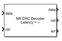
NR CRC Decoder
Detect errors in input data using CRC
Libraries:
Wireless HDL Toolbox /
Error Detection and Correction
Description
The NR CRC Decoder block calculates the cyclic redundancy check (CRC) checksum and compares it with the appended CRC checksum for each frame of streaming data samples. If the two CRC checksums do not match, the block reports an error. The block accepts and returns a data sample stream with accompanying control signals. The control signals indicate the validity of the samples and the boundaries of the frame.
The block supports scalar and vector inputs and outputs data as either a scalar or vector based on the input data. To achieve higher throughput, the block accepts a binary vector or unsigned integer scalar input and implements a parallel architecture. The input data width must be less than or equal to the length of the CRC polynomial, and the length of the CRC polynomial must be divisible by the input data width. The block supports all CRC polynomials specified according to the 5G new radio (NR) standard 3GPP TS 38.212 [1]. When you select the CRC24C polynomial, the block supports dynamic CRC mask.
The block provides an interface and hardware-optimized architecture suitable for HDL code generation and hardware deployment.
Examples

NR CRC Encode and Decode Streaming Data
Use NR CRC Encoder and NR CRC Decoder blocks and compare their hardware-optimized results with results from 5G Toolbox™ functions.
Ports
Input
Output
Parameters
Algorithms
When you use a binary vector or unsigned integer scalar input, the block implements a parallel CRC algorithm [2].
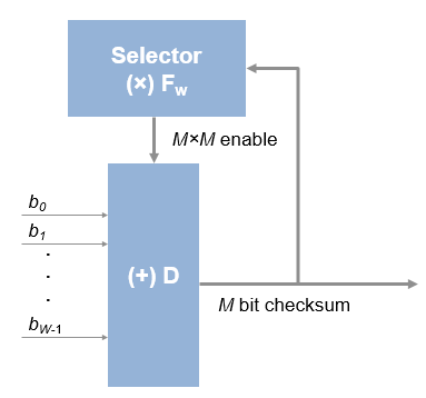
To provide high throughput for modern communications systems, the block implements the CRC algorithm with a parallel architecture. This architecture recursively calculates M bits of a CRC checksum for each W input bits. At the end of the frame, the final checksum result is appended to the message. For a polynomial length of M, the recursive checksum calculation for W bits in parallel is
FW is an M-by-M matrix that selects elements of the current state for the polynomial calculation with the new input bits. D is an M-element vector that provides the new input bits, ordered in relation to the generator polynomial and padded with zeros. The block implements the (×) with logical AND and (+) with logical XOR.
The latency of the block varies with the CRC polynomial length, the type of input (scalar or vector), and the data width of the input. The latency of the block is calculated from the start of the input frame to the start of output frame by using the formula ((CRCLength/N) x 3) + 5 clock cycles, where N is the input data width.
The frame gap between two frames (that is from ctrl.end of the first frame to ctrl.start of the next frame) must be greater than the length of the CRC polynomial plus the latency of the first frame. In case of continuous inputs, the block discards the first frame and starts processing the next frame.
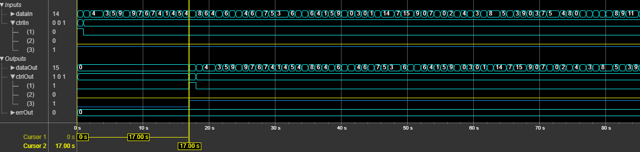
This figure shows a sample output and latency of the NR CRC Decoder
block when you specify a scalar input of data type ufix4 with a data
width of 4, and set the CRC type parameter to
CRC16. The latency of the block is 17 clock cycles, as shown
in this figure.
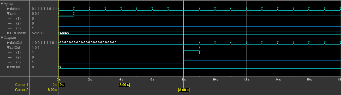
This figure shows a sample output and latency of the NR CRC Decoder
block when you specify a vector input of data type ufix1 with a data
width of 24, set the CRC type parameter to
CRC24C, and select the Enable CRC mask input
port parameter. The latency of the block is 8 clock cycles, as shown in this
figure.
References
[1] 3GPP TS 38.212. “NR; Multiplexing and Channel Coding.” 3rd Generation Partnership Project; Technical Specification Group Radio Access Network.
[2] Campobello, G., G. Patane, and M. Russo. “Parallel CRC Realization.” IEEE Transactions on Computers 52, no. 10 (October 2003): 1312–19. https://doi.org/10.1109/TC.2003.1234528.
Extended Capabilities
Version History
Introduced in R2021a