LTE OFDM Modulator
Modulate LTE resource grid and return time-domain OFDM samples
Libraries:
Wireless HDL Toolbox /
Modulation
Description
The LTE OFDM Modulator block implements an algorithm for modulating LTE resource grid samples specified by LTE standard TS 36.212 [1]. The block uses an orthogonal frequency-division multiplexing (OFDM) mechanism in its operation and converts the resource grid input samples to an equivalent time-domain signal output. OFDM is effective for communication over channels with high-frequency selectivity and is widely used in the development of the LTE downlink transmitter. The block implements a windowing feature to reduce the spectral regrowth, or adjacent channel leakage ratio (ACLR), of an OFDM signal.
The block provides an interface and architecture suitable for HDL code generation and hardware deployment.
You can select the number of downlink resource blocks (NDLRB) and choose either normal or extended cyclic prefix (CP), as described in the LTE standard. The latency from the first input sample to the first output sample depends on your selection of the NDLRB.
| NDLRB | Latency |
|---|---|
| 6 | 6268 |
| 15 | 6376 |
| 25 | 6496 |
| 50 | 6796 |
| 75 | 7096 |
| 100 | 7396 |
Examples

OFDM Modulation of LTE Resource Grid Samples
Use LTE OFDM Modulator block to modulate LTE resource grid samples to equivalent time-domain signal output.
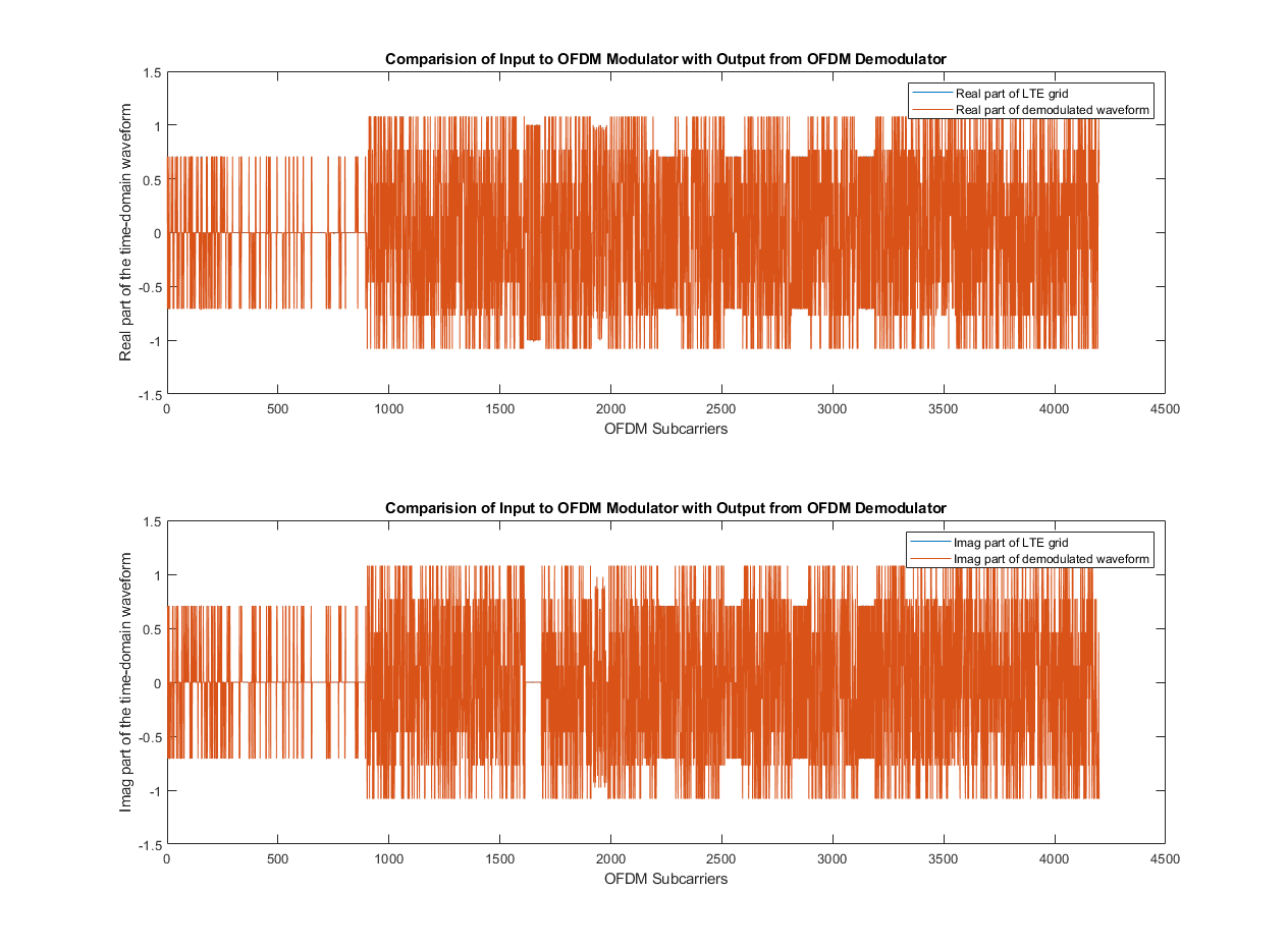
Modulate and Demodulate LTE Resource Grid
Modulate and demodulate LTE resource grid samples.
Ports
Input
Output
Parameters
Algorithms
The LTE OFDM Modulator block operation sequence is carried over using these blocks: OFDM Symbol Formation, IFFT, FFT Shift, CP Addition, Windowing, and Base Rate Controller. The OFDM Symbol Formation block maps the resource grid input to active subcarrier bins to form 2048 subcarriers. The IFFT block converts the frequency-domain signal to time-domain signal, and the FFT Shift block performs time-domain FFT shift. The CP Addition block adds CP-length samples from the end of the symbol to its prefix. The Windowing block performs windowing and overlapping of adjacent OFDM symbols of complex symbols in the resource array. The Base Rate Controller block defines the sample rate of the output data. The parameters shown in the following figure configure the behavior of the block.

An OFDM Symbol Formation subsystem calculates the number of active and inactive subcarriers and the number of CP samples. It generates a ready signal and subcarriers (active, inactive, and DC) for each OFDM symbol as per LTE standard.
The OFDM Symbol Formation subsystem calculates the number of active subcarriers based on the NDLRB value.
Number of active subcarriers = 12 x NDLRB
The number of inactive subcarriers is a difference of IFFT size and the number of active subcarriers. To save hardware resources by avoiding multiple IFFTs, the IFFT size is fixed to 2048.
Number of inactive subcarriers = 2048 — Number of active carriers
The block outputs a signal from ready port to indicate when
the block is ready to accept input data. This signal depends on the
valid input signal, NDLRB, CP type, and OFDM symbol number.
The ready output signal is generated for one time step, and the
valid input signal is checked for next time step. The block
accepts the input data and the ready output signal remains high
(1) until the OFDM symbol data is received. If the
valid input is low (0), the
ready signal extends until the valid
input signal receives high (1). After receiving active
subcarriers, the block sets the ready output signal to low
(0) for a time period equal to the sum of the number of
inactive subcarriers and the number of CP samples.
These figures show Logic Analyzer waveforms of the ready output signal for NDLRB values 25 and 100, respectively.


Cyclic prefix addition is a process of adding the last samples of an OFDM symbol as a prefix to each OFDM symbol. CP addition for an OFDM symbol with Nfft samples and CP samples NCP is shown in this figure.

The LTE OFDM Modulator block uses FFT size of 2048 for all NDLRB resources to avoid multiple IFFTs. The block uses CP values corresponding to NDLRB 100.
The Cyclic prefix type parameter controls whether the block
expects a normal or an extended CP. The block requires the input to maintain a
sample rate of 30.72 MHz. It assumes that each symbol is 2048 samples plus the
cyclic prefix size associated with the rate. When using a normal CP, the prefix of
the first symbol in each slot has 160 samples, while each subsequent symbol contains
a prefix of 144 samples. When using an extended CP, all symbols contain 512 samples.
For more information about the cyclic prefix length (in samples) of each OFDM symbol
in a subframe, see the lteOFDMModulate (LTE Toolbox) function.
This block generates the output data at a sample rate of 30.72 MHz by using the maximum output data sample rate or output data sample rate with the specified NDLRB.
This figure shows a Logic Analyzer waveform of the output data when you set the
Output data sample rate parameter to Use
maximum output data sample rate.

This figure shows a Logic Analyzer waveform of the output data when you set the
Output data sample rate parameter to Match
output data sample rate to NDLRB parameter. For NDLRB value 25,
the output sample rate is 7.68 MHz, and the block returns valid output data at every
fourth cycle.

References
[1] 3GPP TS 36.212. "Multiplexing and channel coding." 3rd Generation Partnership Project; Technical Specification Group Radio Access Network; Evolved Universal Terrestrial Radio Access (E-UTRA). URL: https://www.3gpp.org.
Extended Capabilities
Version History
Introduced in R2019a