3 次元点群のレジストレーションと繋ぎ合わせ
この例では、反復最近接点 (ICP) アルゴリズムにより複数の点群を組み合わせて 3 次元シーンを再構成する方法を説明します。次に、点群で利用可能な色情報を活用してシーンの精度を向上させる方法を示します。
概要
この例では、Kinect を使ってキャプチャした点群の集合を繋ぎ合わせて、より大きいシーンの 3 次元ビューを構成します。例では ICP が 2 つの連続する点群に適用されます。このタイプの再構成は、オブジェクトの 3 次元モデルを開発したり、自己位置推定と環境地図作成の同時実行 (SLAM) に使用する 3 次元世界地図を作成するのに使用できます。
点群データの読み込み
点群データは、pointCloudオブジェクトの cell 配列として利用できます。データを一時ディレクトリにダウンロードします。
dataURL = "https://www.mathworks.com/supportfiles/vision/data/livingRoom.mat";
pointCloudFolder = fullfile(tempdir,"pointCloudDataRegistrationAndStitching");
pointCloudData = fullfile(pointCloudFolder,"livingRoom.mat");

% Download the point cloud data.
if ~exist(pointCloudData,"file")
    if ~exist(pointCloudFolder,"dir")
        mkdir(pointCloudFolder);
    end
    disp("Downloading point cloud data (5.5 MB)...");
    websave(pointCloudData,dataURL);
end
% Load the point cloud data.
load(pointCloudData);

% Extract two consecutive point clouds to use the first point cloud as
% reference.
ptCloudRef = livingRoomData{1};
ptCloudCurrent = livingRoomData{2};
2 つの点群のレジストレーション
レジストレーションの質は、データのノイズおよび ICP アルゴリズムの初期設定によって異なります。前処理手順を適用してノイズをフィルター処理するか、データに適した初期プロパティ値を設定することができます。ここでは、グリッドのサイズを 0.1 m に設定し、グリッドに最も近いフィルターを使用したダウンサンプリングによりデータを前処理します。グリッド フィルターは点群の空間をボクセルに分割します。各ボクセルに対して、ボクセルの重心に最も近い点を選択します。
gridSize = 0.1;
fixed = pcdownsample(ptCloudRef,gridNearest=gridSize);
moving = pcdownsample(ptCloudCurrent,gridNearest=gridSize);
ダウンサンプリングの手順により、レジストレーションが高速化されるだけでなく、精度も向上する可能性があります。
2 つの点群の位置を合わせるには、点対平面 ICP アルゴリズムを使って、ダウンサンプリングされたデータに対し 3 次元剛体変換の推定を行います。最初の点群を参照として使用し、推定された変換を元の 2 番目の点群に適用します。シーンの点群を位置合わせした点群とマージして、オーバーラップする点を処理します。
まず、2 番目の点群を最初の点群と位置合わせするための剛体変換を求めます。これを使用して、2 番目の点群を、最初の点群によって定義された参照座標系に変換します。
tform = pcregistericp(moving,fixed,Metric="pointToPlane");
ptCloudAligned = pctransform(ptCloudCurrent,tform);
これで、レジストレーション済みのデータを使ってワールド シーンを作成できるようになりました。オーバーラップする領域は、0.015 m のボックス グリッド フィルターでフィルター処理されます。結果として得られるシーンの点群で必要とされるストレージ容量を抑えるにはマージ サイズを大きくし、シーンの解像度を高めるにはマージ サイズを小さくします。
mergeSize = 0.015;
ptCloudScene1 = pcmerge(ptCloudRef,ptCloudAligned,mergeSize);

% Visualize the input images.
figure
subplot(2,2,1)
imshow(ptCloudRef.Color)
title("First input image",Color="w")

subplot(2,2,3)
imshow(ptCloudCurrent.Color)
title("Second input image",Color="w")

% Visualize the world scene.
subplot(2,2,[2,4])
pcshow(ptCloudScene1,VerticalAxis="Y",VerticalAxisDir="Down")
title("Initial world scene")
xlabel("X (m)")
ylabel("Y (m)")
zlabel("Z (m)")

点群のシーケンスの繋ぎ合わせ
より大きな 3 次元シーンを作成するには、上記と同じ手続きを繰り返して点群のシーケンスを処理します。最初の点群を使用して、参照座標系を規定します。各点群を参照座標系に変換します。この変換はペアワイズ変換の乗算です。
% Store the transformation object that accumulates the transformation.
accumTform = tform;

figure
hAxes = pcshow(ptCloudScene1,VerticalAxis="Y",VerticalAxisDir="Down");
title("Updated world scene")
xlabel("X (m)")
ylabel("Y (m)")
zlabel("Z (m)")

% Set the axes property for faster rendering.
hAxes.CameraViewAngleMode = "auto";
hScatter = hAxes.Children;

for i = 3:length(livingRoomData)
    ptCloudCurrent = livingRoomData{i};

    % Use previous moving point cloud as reference.
    fixed = moving;
    moving = pcdownsample(ptCloudCurrent,gridNearest=gridSize);

    % Apply ICP registration.
    tform = pcregistericp(moving,fixed,Metric="pointToPlane");

    % Transform the current point cloud to the reference coordinate system
    % defined by the first point cloud.
    accumTform = rigidtform3d(accumTform.A * tform.A);
    ptCloudAligned = pctransform(ptCloudCurrent,accumTform);

    % Update the world scene.
    ptCloudScene1 = pcmerge(ptCloudScene1,ptCloudAligned,mergeSize);

    % Visualize the world scene.
    hScatter.XData = ptCloudScene1.Location(:,1);
    hScatter.YData = ptCloudScene1.Location(:,2);
    hScatter.ZData = ptCloudScene1.Location(:,3);
    hScatter.CData = ptCloudScene1.Color;
    drawnow("limitrate")
end

記録中、Kinect は下を向いていました。グランド プレーンが X-Z 面と平行になるようにシーンを変換します。
angle = -10;
translation = [0 0 0];
tform = rigidtform3d([angle 0 0],translation);
ptCloudScene1 = pctransform(ptCloudScene1,tform);
プロットのカメラ角度を変更して、繋ぎ合わされた結果をより詳しく検査します。
hAxes1 = pcshow(ptCloudScene1,AxesVisibility="off");
hAxes1.CameraPosition = [-0.6 0.2 0.5];
hAxes1.CameraTarget = [1.3 0.5 0.3];
hAxes1.CameraUpVector = [0.2 -0.9 -0.1];
hAxes1.CameraViewAngle = 60;
繋ぎ合わされたシーンは位置が合っているように見えますが、シーンの一部にドリフトがあり、より詳しく検査するとそれが目立ちます。たとえば、パンダの近くにある机の上の花は位置が合っていません。用途によっては、シーンの精度をさらに向上させたい場合があります。結果を改善するには、名前と値の引数 Metric を "planeToPlane" に設定して ICP アルゴリズムを使用してみることができます。あるいは、点群に色情報が含まれている場合、それを使用して 3 次元シーンの精度を向上させることができます。
色情報を使用した点群のシーケンスの繋ぎ合わせ
関数 pcregistericp は、名前と値の引数 Metric が "pointToPlaneWithColor" または "planeToPlaneWithColor" に設定されているときに点群の色情報を使用します。関数 helperStitchPointCloudsUsingColor は、名前と値の引数 Metric を "pointToPlaneWithColor" に設定して、前のセクションの手順を繰り返します。
色情報を使用して点群シーケンスを繋ぎ合わせます。
ptCloudScene2 = helperStitchPointCloudsUsingColor(livingRoomData);
更新されたワールド シーンを可視化します。
figure
pcshow(ptCloudScene2,VerticalAxis="Y",VerticalAxisDir="Down")
title("Updated world scene with registration using color information")
xlabel("X (m)")
ylabel("Y (m)")
zlabel("Z (m)")

プロットのカメラ角度を変更して、繋ぎ合わされた結果をより詳しく検査します。
hAxes2 = pcshow(ptCloudScene2,AxesVisibility="off");
hAxes2.CameraPosition = [-12.6 -2.9 -0.9];
hAxes2.CameraTarget = [27.3 7.4 3.6];
hAxes2.CameraUpVector = [0.27 -0.93 -0.24];
hAxes2.CameraViewAngle = 11;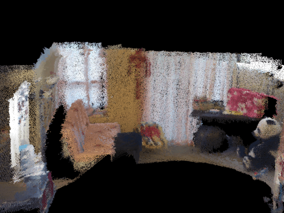
点群で利用可能な色情報を活用することで、繋ぎ合わされたシーンのドリフトが減少しました。たとえば、結果の 3 次元シーンでは、パンダの隣の花の配置が改善されました。
まとめ
この例では、ICP 点群のレジストレーションを使用して複数の点群を繋ぎ合わせ、3 次元シーンを再構成する方法を示します。また、ICP を使用して点群に存在する色情報を活用し、再構成されたシーンの精度を向上させる方法も示します。
サポート関数
関数 helperStitchPointCloudsUsingColor は、関数 pcregistericp と "pointToPlaneWithColor" メトリクスを使用して複数の点群を繋ぎ合わせることにより、再構成されたワールド シーンを返します。
function ptCloudScene = helperStitchPointCloudsUsingColor(livingRoomData)

% Extract the first point cloud as reference.
ptCloudRef = livingRoomData{1};

% Downsample the point cloud.
gridSize = 0.1;
moving = pcdownsample(ptCloudRef,gridNearest=gridSize);

% Set the merge size to merge each point cloud to the scene.
mergeSize = 0.015;
ptCloudScene = ptCloudRef;

% Store the transformation object that accumulates the transformation.
accumTform = rigidtform3d();

for i = 2:length(livingRoomData)
    ptCloudCurrent = livingRoomData{i};

    % Use previous moving point cloud as reference.
    fixed = moving;
    moving = pcdownsample(ptCloudCurrent,gridNearest=gridSize);

    % Apply ICP registration.
    tform = pcregistericp(moving,fixed,Metric="pointToPlaneWithColor",InlierDistance=0.1);

    % Transform the current point cloud to the reference coordinate system
    % defined by the first point cloud.
    accumTform = rigidtform3d(accumTform.A * tform.A);
    ptCloudAligned = pctransform(ptCloudCurrent,accumTform);

    % Update the world scene.
    ptCloudScene = pcmerge(ptCloudScene,ptCloudAligned,mergeSize);
end

% During the recording, the Kinect was pointing downward.
% Transform the scene so that the ground plane is parallel
% to the X-Z plane.
angle = -10;
translation = [0 0 0];
tform = rigidtform3d([angle 0 0],translation);
ptCloudScene = pctransform(ptCloudScene,tform);
end