verifyImagePairs
R2026bDescription
The verifyImagePairs function refines the SfM view graph
created by the connectImagePairs function by enforcing epipolar
constraints to remove geometrically inconsistent connections. Use the
verifyImagePairs object function as the second step in the SfM
pipeline, followed by the triangulateInitialViews object function, which
initializes the 3-D reconstruction. Use the isConnected function to
verify whether the view graph is ready for refinement before calling the
verifyImagePairs function.
The verifyImagePairs function uses the essential matrix and homography
as geometric models while refining the connections in the view graph. For more information
about the algorithm see Algorithms.
sfmObj = verifyImagePairs(sfmObj)sfm object
sfmObj by using epipolar constraints. After verification, the view
graph contains only connections between image pairs whose feature matches are consistent with
valid camera motion. The function then returns a version of the input SfM object with
updated ViewGraph, SimilarityMatrix, and ConnectedImages
property values.
sfmObj = verifyImagePairs(sfmObj,Name=Value)verifyImagePairs(sfmObj,MinNumInliers=50) requires that a connection
have at least 50 inlier matches to be considered valid and retained in the
view graph.
Examples
Use the sfm object to recover camera poses and a sparse 3-D point cloud from images of an indoor scene.
Create Image Datastore and Define Camera Intrinsics
Create an ImageDatastore from the image sequence. Specify the camera intrinsic parameters.
unzip("sfm_images.zip")
imageFolder = fullfile(pwd,"images");
imds = imageDatastore(imageFolder);
intrinsics = cameraIntrinsics([535.1307 532.1860],[323.3722 239.7986],[480 640]);
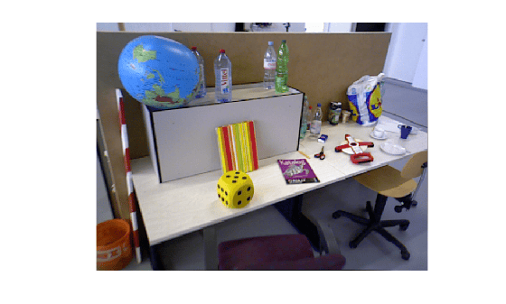
Visualize the indoor scene.
imshow(preview(imds))
Create SfM Object and Run Pipeline
Create an sfm object and execute each stage of the incremental SfM pipeline sequentially.
sfmObj = sfm(imds,intrinsics);
Connect image pairs based on visual similarity.
sfmObj = connectImagePairs(sfmObj);
Visualize the similarity matrix for the connected image pairs using the imagesc function.
imagesc(sfmObj.SimilarityMatrix)
title("Similarity Matrix for Connected Image Pairs")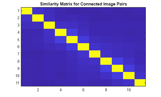
Verify that the view graph was created successfully before proceeding to geometric verification.
if isConnected(sfmObj)
    sfmObj = verifyImagePairs(sfmObj);
end
Visualize the similarity matrix for the refined image pair connections using the imagesc function.
imagesc(sfmObj.SimilarityMatrix)
title("Similarity Matrix after Refining Connected Image Pairs")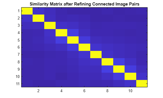
Confirm that geometric verification completed successfully before initializing the reconstruction. Specify a minimum median angle of 5 degrees and a maximum triangulation error of 4 pixels. Display the initialization metrics.
if isVerified(sfmObj)
    [sfmObj,info] = triangulateInitialViews(sfmObj,MinMedianAngle=5,MaxTriangulationError=4);
    disp(info)
end
                     ViewId1: 9
                     ViewId2: 10
                RelativePose: [1×1 rigidtform3d]
                     Matches: [380×2 uint32]
    MedianTriangulationAngle: 8.6016
       MeanReprojectionError: 0.2799
Confirm that initialization succeeded before running incremental reconstruction.
if isInitialized(sfmObj)
    sfmObj = reconstruct(sfmObj);
end
Retrieve Results
Retrieve the estimated camera poses and the sparse 3-D point cloud.
camPoses = poses(sfmObj);
sparsePoints = pointCloud(sfmObj);
Visualize Reconstruction
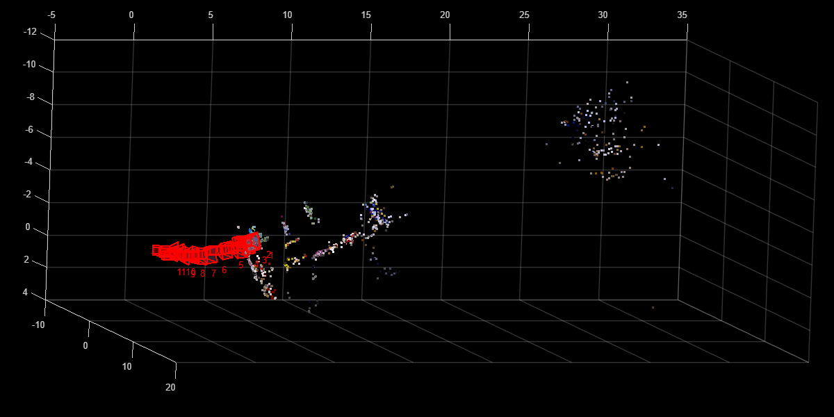
Display the reconstructed scene showing the camera trajectory and sparse point cloud. Adjust the view orientation and zoom for better visualization.
plot(sfmObj,CameraSize=0.5,MarkerSize=25)
view(82.69,-15.53)
camroll(-90)
camva(4.52)
This example shows you how to analyze and visualize the results of the verifyImagePairs function.
Create Image Datastore and Define Camera Intrinsics
Create an imageDatastore object from the image sequence. Specify the camera intrinsics parameters.
unzip("sfm_images.zip")
imageFolder = fullfile(pwd,"images");
imds = imageDatastore(imageFolder);
intrinsics = cameraIntrinsics([535.1307 532.1860],[323.3722 239.7986],[480 640]);
Visualize images in the sequence.
figure
montage(imds)
title("Image Sequence")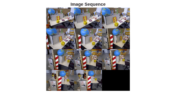
Create sfm Object and Connect Similar Images
Initialize the sfm object with the image datastore and camera intrinsics. As the first step in the SfM process, create a view graph by connecting visually similar image pairs.
sfmObj = sfm(imds,intrinsics);
sfmObjViewGraph = connectImagePairs(sfmObj);
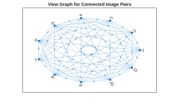
Visualize the view graph showing images as nodes and edges connecting visually similar image pairs.
G1 = createPoseGraph(sfmObjViewGraph.ViewGraph);
figure
plot(G1, NodeLabel=1:sfmObjViewGraph.NumImages, Layout="circle");
title("View Graph for Connected Image Pairs");
Refine View Graph Using Geometric Verification
Refine the view graph by removing edges that violate epipolar geometric constraints.
sfmObjRefined = verifyImagePairs(sfmObjViewGraph, Verbose=true);
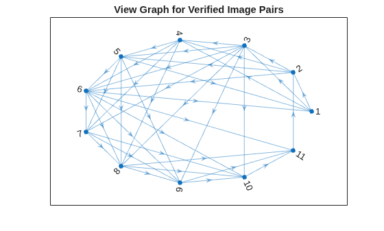
39 out of 54 edges passed geometric verification.
Avearge 2D inliers count: 179.512821
Mininum 2D inliers count: 33
Maximum 2D inliers count: 470
Visualize the view graph after geometric verification. Observe that there are fewer spurious edges in this refined graph compared to the initial sfmObjViewGraph object.
G2 = createPoseGraph(sfmObjRefined.ViewGraph);
figure
plot(G2, NodeLabel=1:sfmObjRefined.NumImages, Layout="circle");
title("View Graph for Verified Image Pairs");
Visualize Matched Features Between Image Pairs
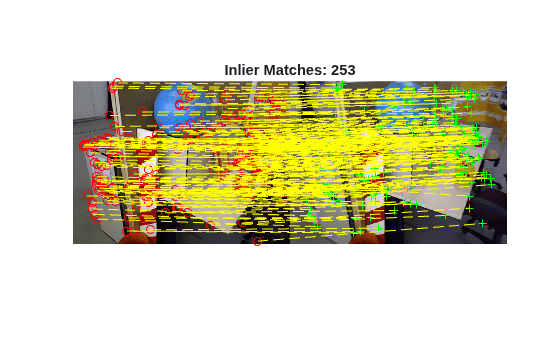
Visualize matched features for a selected connection. Note that the geometric verification has removed outliers from the initial feature matches.
Pick one of the image pairs and visualize the matched features. The connId variable specifies the index of view graph edge connecting the image pair being visualized.
connId =24; viewId1 = sfmObjRefined.ViewGraph.Connections.ViewId1(connId); viewId2 = sfmObjRefined.ViewGraph.Connections.ViewId2(connId); % Read image pair I1 = readimage(imds, viewId1); I2 = readimage(imds, viewId2); % Get the matched feature points matchedPairs = sfmObjRefined.ViewGraph.Connections.Matches{connId}; points1 = sfmObjRefined.ViewGraph.Views.Points{viewId1}; points2 = sfmObjRefined.ViewGraph.Views.Points{viewId2}; matchedPoints1 = points1(matchedPairs(:,1)); matchedPoints2 = points2(matchedPairs(:,2)); figure showMatchedFeatures(I1, I2, matchedPoints1, matchedPoints2, "montage", PlotOptions={"ro","g+","y--"}); title("Inlier Matches: " + matchedPoints1.Count);
Effect of MinNumInliers on View Graph Connectivity
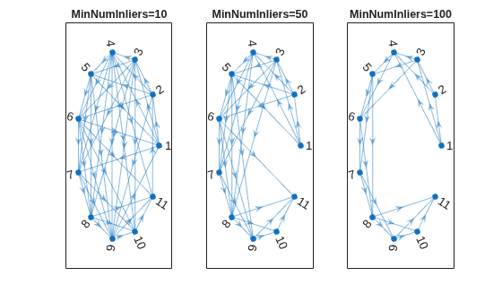
The value of the MinNumInliers name-value argument controls the number of matching inlier points between two images for them to be considered a valid connection in the view graph.
Create three instances of the sfm object by calling verifyImagePairs with different values of MinNumInliers.
sfmObjInlier10 = verifyImagePairs(sfmObjViewGraph, MinNumInliers=10);
sfmObjInlier50 = verifyImagePairs(sfmObjViewGraph, MinNumInliers=50);
sfmObjInlier100 = verifyImagePairs(sfmObjViewGraph, MinNumInliers=100);
Visualize the view graphs obtained by specifying increasing values of MinNumInliers. Observe that higher values apply a stricter criterion for a valid match between image pairs, resulting in sparser, but more geometrically accurate, connections between images. Decrease this value to relax the verification conditions in challenging cases such as when images have limited overlaps in their field of view.
G10 = createPoseGraph(sfmObjInlier10.ViewGraph);
G50 = createPoseGraph(sfmObjInlier50.ViewGraph);
G100 = createPoseGraph(sfmObjInlier100.ViewGraph);

figure
subplot(1,3,1)
plot(G10, NodeLabel=1:sfmObj.NumImages, Layout="circle");
title("MinNumInliers=10");

subplot(1,3,2)
plot(G50, NodeLabel=1:sfmObj.NumImages, Layout="circle");
title("MinNumInliers=50");

subplot(1,3,3)
plot(G100, NodeLabel=1:sfmObj.NumImages, Layout="circle");
title("MinNumInliers=100");
Effect of MaxDistance on View Graph Connectivity
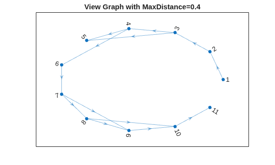
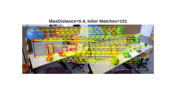
Matched points between two images having a geometric inconsistency more than the value in pixels specified by the MaxDistance name-value argument are considered outliers. Smaller values of MaxDistance produce fewer matched inlier points between image pairs, resulting in fewer image pairs remaining connected after verification. Increase this value to relax the verification criterion in challenging cases such as blurry images or large camera motions.
Select different values of MaxDistance and visualize both the resulting view graph and inlier matches between a pair of images.
maxDist =0.4; sfmObjMaxDist = verifyImagePairs(sfmObjViewGraph, MaxDistance=maxDist); % Select the first edge of the view graph connId = 1; viewId1 = sfmObjMaxDist.ViewGraph.Connections.ViewId1(connId); viewId2 = sfmObjMaxDist.ViewGraph.Connections.ViewId2(connId); % Read image pair I1 = readimage(imds, viewId1); I2 = readimage(imds, viewId2); % Get the matched feature points matchedPairs = sfmObjMaxDist.ViewGraph.Connections.Matches{connId}; points1 = sfmObjMaxDist.ViewGraph.Views.Points{viewId1}; points2 = sfmObjMaxDist.ViewGraph.Views.Points{viewId2}; matchedPoints1 = points1(matchedPairs(:,1)); matchedPoints2 = points2(matchedPairs(:,2));
Reducing the value of MaxDistance creates a sparser view graph while increasing it creates more edges between nodes.
figure
Gdist = createPoseGraph(sfmObjMaxDist.ViewGraph);
plot(Gdist, NodeLabel=1:sfmObj.NumImages, Layout="circle");
title("View Graph with MaxDistance=" + maxDist);
Reducing the value of MaxDistance results in fewer inlier matches as visualized in the selected image pair. Increasing this value results in more matching points being accepted as inliers.
Visualize the matched points between the image pair in the first connection of the view graph.
figure
showMatchedFeatures(I1, I2, matchedPoints1, matchedPoints2, "montage", PlotOptions={"ro","g+","y--"});
title("MaxDistance=" + maxDist + ", Inlier Matches=" + matchedPoints1.Count);
Input Arguments
Name-Value Arguments
Output Arguments
Tips
To assess how many connections the function removes during refinement, compare the
SimilarityMatrixproperties of the input and outputsfmobjects by using theimagescfunction.If refinement removes too many connections, reduce the value of the
MinNumInliersargument, or increase the value of theMaxDistanceargument.If too many false pairs survive verification, increase the value of the
MinNumInliersargument, or decrease the value of theMaxDistanceargument.For more information, see Best Practices for 3-D Reconstruction Using Structure from Motion.
Algorithms
After the SfM pipeline connects image pairs using appearance‑based feature matching, geometric verification enforces consistency with the underlying camera geometry. This step removes incorrect or spurious connections by validating feature correspondences against epipolar constraints. By filtering out geometrically inconsistent image pairs, the algorithm refines the view graph to retain only robust, physically plausible connections, improving the stability and accuracy of subsequent 3‑D reconstruction.
For each connected image pair in the view graph, the verifyImagePairs
function performs these steps:
Estimate geometric models — The function estimates the essential matrix using the five‑point algorithm within a RANSAC framework to model general 3‑D scene geometry. In parallel, it estimates a homography using RANSAC to model planar or near‑planar scenes.
Select the appropriate geometric model — The function evaluates both geometric models and compares their inlier counts. It selects the model with the higher number of inliers, indicating that the image pair is better explained by the selected geometry. A higher inlier count for the essential matrix indicates a general 3‑D scene structure, while a higher inlier count for the homography indicates planar geometry or pure camera rotation.
Identify geometrically consistent matches — Using the selected geometric model, the function identifies inlier feature correspondences that satisfy the estimated epipolar or homography constraints.
Refine the view graph — The function retains the image pair in the view graph if the number of inlier correspondences meets a minimum inlier requirement. If the number of inliers falls below this threshold, the function removes the image pair from the view graph.
Version History
Introduced in R2026b
See Also
sfm | connectImagePairs | isConnected | isVerified | triangulateInitialViews | reconstruct | poses | pointCloud | plot | isInitialized

