Implement Slower Execution Rates for Blocks in a Single-Rate Model
This example shows how to use the UAV Toolbox Support Package for ArduPilot® Autopilots to run selected blocks at slower effective rates within a single-rate Simulink model. The support package enforces a single fixed-step execution rate, determined by the main loop frequency of the ArduPilot firmware. As a result, all blocks in the model execute at this base rate. For example, 2.5 ms (400 Hz) for Copter and 20 ms (50 Hz) for Plane.
In some cases, certain computations need to run at a slower effective rate, such as 100 Hz or 20 Hz without changing the model’s base rate. This can be accomplished by placing the desired blocks inside an Enabled Subsystem, which is triggered by a Pulse Generator configured to enable the subsystem at a specified interval.
This example demonstrates how to:
Use an Enabled Subsystem to execute selected blocks only when triggered.
Trigger the subsystem with a Pulse Generator that generates enable signals at a multiple of the base rate.
Run different parts of the model at effective rates that are integer multiples of the base rate.
Prerequisites
Before you begin, complete the following.
If you are new to Simulink, watch the Simulink Quick Start video.
Complete the hardware setup. For more information, see Install UAV Toolbox Support Package for ArduPilot Autopilots in Windows.
Required Hardware
To run this example, you will need the following hardware:
ArduPilot supported Autopilot. This example uses Cube Orange.
Configure the Model
The preconfigured Simulink model, SlowerRatesWithEnabledSubsystem.slx, is set up with the ArduPilot Host target as the hardware.
Open the SlowerRatesWithEnabledSubsystem.slx Simulink® model.
modelName = "SlowerRatesWithEnabledSubsystem";
open_system(modelName)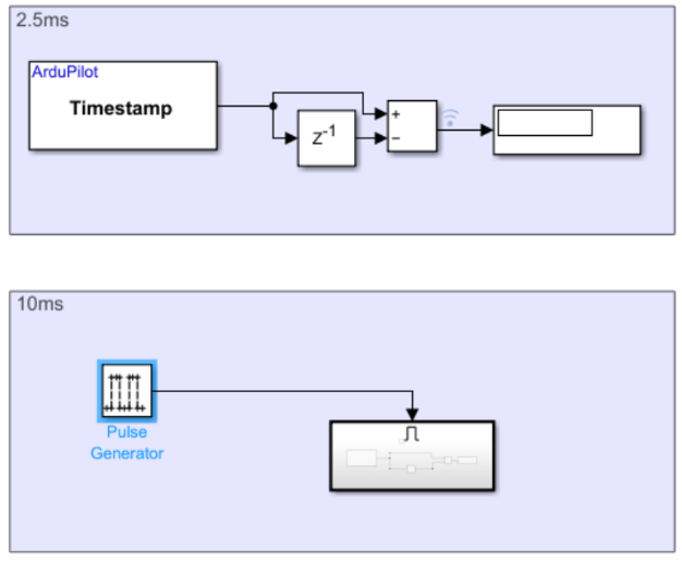
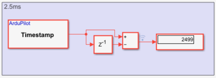
The model measures the effective execution interval of a subsystem in Simulink by using a Time Stamp block, a Unit Delay, and a subtraction operation. This interval shows the amount of simulation time that passes between two executions of the subsystem.
Time measurement logic is included both at the base rate and inside an enabled subsystem, enabling the observation of different effective sample times.
Note: Set the vehicle type to ArduCopter in the model configuration before running the example.
Run the Model in Monitor and Tune Simulation
On the Hardware tab, in the Mode section, click Run on board and then select Run on board (External mode). If you see Connected IO selected instead of Run on board, click on it and choose Run on board (External mode).
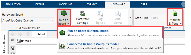
2. Click Monitor & Tune to observe signal values and adjust parameters.
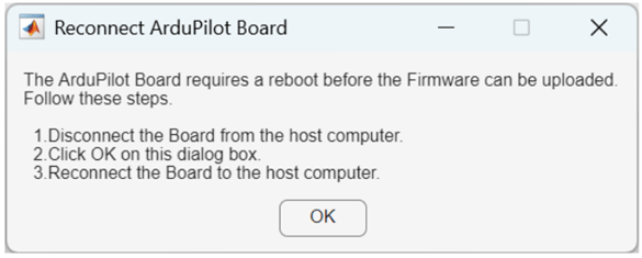
3. After the build completes, you will be prompted to reconnect your hardware in order to flash the generated executable. A pop-up window will be displayed with instructions.
Once the model starts running, observe the outputs on the display blocks in the model.
Base Rate Execution
When the measurement logic operates at the model’s base rate:
The base sample time is 2.5 ms for ArduCopter.
The Time Stamp block outputs the current simulation time at every base rate step.
The difference between consecutive time stamps equals the base sample time.
The Display block shows a constant value of 2500 µs (2.5 ms).
This behavior confirms that the subsystem is executing at the model’s base rate.
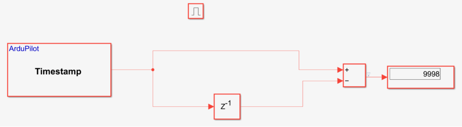
Slower Execution Using an Enabled Subsystem
When the measurement logic is placed inside an Enabled Subsystem triggered by a Pulse Generator every four base rate ticks:
The base rate remains 2.5 ms.
The enable signal activates the subsystem once every 4 × 2.5 ms = 10 ms.
The Time Stamp block updates only when the subsystem is enabled.
The difference between consecutive time stamps equals 10 ms.
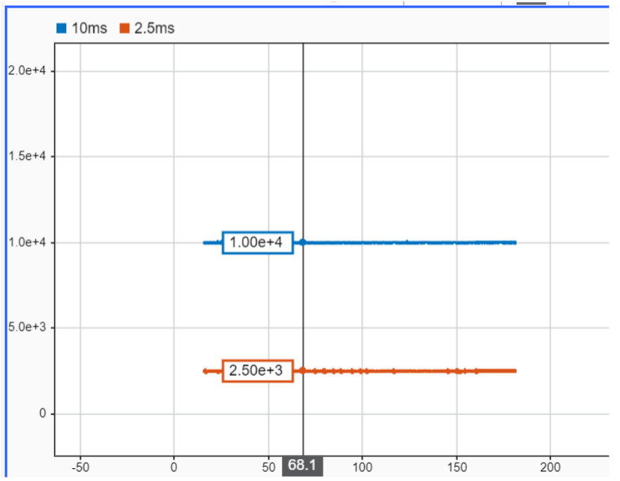
The Display block shows a constant value of approximately 10,000 µs (10 ms).
This behavior demonstrates that the effective sample time of the subsystem is determined by the enable signal, rather than the global base rate.
The same behavior can also be observed in the Simulink Data Inspector.