systemcomposer.arch.ComponentPort
Component port
Description
A ComponentPort object represents the input, output, and
physical ports of a System Composer™ component. This class inherits from systemcomposer.arch.BasePort. This class is derived from systemcomposer.arch.Element.
Creation
A component port is constructed by creating an architecture port on the architecture of
the component using the addPort
function, then getting the component port using the getPort
function.
addPort(compObj.Architecture,'portName','in');
compPortObj = getPort(compObj,'portName');
Properties
Object Functions
setName | Set name for port |
connect | Create architecture model connections |
getConnectorTo | Find connector between ports |
setInterface | Set interface for port |
createInterface | Create and set owned interface for port |
applyStereotype | Apply stereotype to model element |
getStereotypes | Get stereotypes applied on model element |
changeStereotype | Change currently applied stereotype to new stereotype in its stereotype hierarchy |
removeStereotype | Remove stereotype from model element |
setProperty | Set property value corresponding to stereotype applied to element |
getProperty | Get property value corresponding to stereotype applied to element |
getPropertyValue | Get value of architecture property |
getEvaluatedPropertyValue | Get evaluated value of property from element |
getStereotypeProperties | Get stereotype property names on element |
hasStereotype | Find if element has stereotype applied |
hasProperty | Find if element has property |
getQualifiedName | Get model element qualified name |
lookup | Search for architectural element |
current | Get object of currently selected element |
Examples
To build an architecture model programmatically using System Composer™, add a data dictionary with data interfaces, data elements, a value type, and a physical interface, and then add components, ports, and connections. Create a profile with stereotypes and properties, and then apply those stereotypes to model elements. Assign an owned interface to a port. After the model is built, you can create custom views to focus on specific considerations. You can also query the model to collect different model elements according to criteria you specify.
Add Components, Ports, Connections, and Interfaces
Create a model and extract its architecture.
model = systemcomposer.createModel("mobileRobotAPI");
arch = model.Architecture;
Create a data dictionary and add a data interface. Add a data element to the data interface. Add a value type to the data dictionary. Assign the type of the data element to the value type. Add a physical interface and physical element with a physical domain type. Link the data dictionary to the model.
dictionary = systemcomposer.createDictionary("SensorInterfaces.sldd");
interface = dictionary.addInterface("GPSInterface");
element = interface.addElement("SignalStrength");
valueType = dictionary.addValueType("SignalStrengthType",Units="dB", ...
    Description="GPS Signal Strength");
element.setType(valueType);
physicalInterface = dictionary.addPhysicalInterface("PhysicalInterface");
physicalElement = addElement(physicalInterface,"ElectricalElement", ...
    Type="electrical.electrical");
linkDictionary(model,"SensorInterfaces.sldd");
Save the changes to the data dictionary.
dictionary.save
Save the model.
model.save
Open the model.
systemcomposer.openModel("mobileRobotAPI");View the interfaces in the Interface Editor.
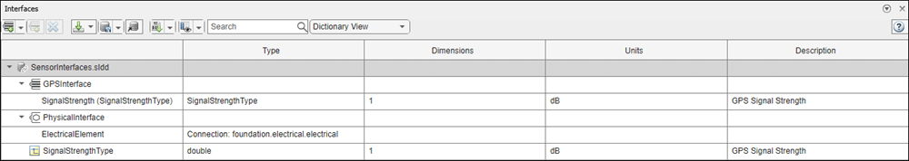
Add components, ports, and connections. Set the physical interface to the physical ports, which you connect later.
componentSensor = addComponent(arch,"Sensor");
sensorPorts = addPort(componentSensor.Architecture,{'MotionData','SensorPower'}, ...
    {'in','physical'});
sensorPorts(2).setInterface(physicalInterface)

componentPlanning = addComponent(arch,"Planning");
planningPorts = addPort(componentPlanning.Architecture, ...
    {'Command','SensorPower1','MotionCommand'}, ...
    {'in','physical','out'});
planningPorts(2).setInterface(physicalInterface)

componentMotion = addComponent(arch,"Motion");
motionPorts = addPort(componentMotion.Architecture,{'MotionCommand','MotionData'}, ...
    {'in','out'});
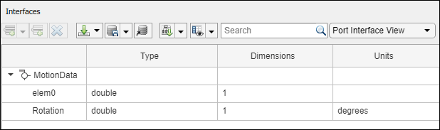
Create an owned interface on the MotionData port. Add an owned data element under the owned data interface. Assign the data element Rotation to a value type with units set to degrees.
ownedInterface = motionPorts(2).createInterface("DataInterface");
ownedElement = ownedInterface.addElement("Rotation");
subInterface = ownedElement.createOwnedType(Units="degrees");
View the interfaces in the Interface Editor. Select the MotionData port on the Motion component. In the Interface Editor, switch from Dictionary View to Port Interface View.
Connect components with an interface rule and the default name rule. The interface rule connects ports on components that share the same interface. By default, the name rule connects ports on components that share the same name.
c_sensorData = connect(arch,componentSensor,componentPlanning,Rule="interface");
c_motionData = connect(arch,componentMotion,componentSensor);
c_motionCommand = connect(arch,componentPlanning,componentMotion);
Add and Connect Architecture Port
Add an architecture port on the architecture.
archPort = addPort(arch,"Command","in");
The connect command requires a component port as an argument. Obtain the component port, and then connect it.
compPort = getPort(componentPlanning,"Command");
c_Command = connect(archPort,compPort);
Save the model.
model.save
Arrange the layout by pressing Ctrl+Shift+A, or use this command.
Simulink.BlockDiagram.arrangeSystem("mobileRobotAPI"); 
Create and Apply Profile with Stereotypes
Profiles are XML files that you can apply to any model. You can add stereotypes with properties to profiles and then populate the properties with specific values in the Profile Editor. Along with the built-in analysis capabilities of System Composer, stereotypes help you optimize your system for performance, cost, and reliability.
Create Profile and Add Stereotypes
Create a profile.
profile = systemcomposer.createProfile("GeneralProfile");Create a stereotype that applies to all element types.
elemSType = addStereotype(profile,"projectElement");Create stereotypes for different types of components. You select these types according to your design needs.
pCompSType = addStereotype(profile,"physicalComponent",AppliesTo="Component");
sCompSType = addStereotype(profile,"softwareComponent",AppliesTo="Component");
Create a stereotype for connections.
sConnSType = addStereotype(profile,"standardConn",AppliesTo="Connector");
Add Properties
Add properties to the stereotypes. You can use properties to capture metadata for model elements and analyze nonfunctional requirements. These properties are added to all elements to which the stereotype is applied, in any model that imports the profile.
addProperty(elemSType,'ID',Type="uint8");
addProperty(elemSType,'Description',Type="string");
addProperty(pCompSType,'Cost',Type="double",Units="USD");
addProperty(pCompSType,'Weight',Type="double",Units="g");
addProperty(sCompSType,'develCost',Type="double",Units="USD");
addProperty(sCompSType,'develTime',Type="double",Units="hour");
addProperty(sConnSType,'unitCost',Type="double"',Units="USD");
addProperty(sConnSType,'unitWeight',Type="double",Units="g");
addProperty(sConnSType,'length',Type="double",Units="m");
Save Profile
profile.save;
Apply Profile to Model
Apply the profile to the model.
applyProfile(model,"GeneralProfile");Apply stereotypes to components. Some components are physical components, while others are software components.
applyStereotype(componentPlanning,"GeneralProfile.softwareComponent")
applyStereotype(componentSensor,"GeneralProfile.physicalComponent")
applyStereotype(componentMotion,"GeneralProfile.physicalComponent")
Apply the connector stereotype to all connections.
batchApplyStereotype(arch,'Connector',"GeneralProfile.standardConn");
Apply the general element stereotype to all connectors and ports.
batchApplyStereotype(arch,'Component',"GeneralProfile.projectElement");
batchApplyStereotype(arch,'Connector',"GeneralProfile.projectElement");
Set properties for each component.
setProperty(componentSensor,'GeneralProfile.projectElement.ID','001');
setProperty(componentSensor,'GeneralProfile.projectElement.Description', ...
    'Central unit for all sensors');
setProperty(componentSensor,'GeneralProfile.physicalComponent.Cost','200');
setProperty(componentSensor,'GeneralProfile.physicalComponent.Weight','450');
setProperty(componentPlanning,'GeneralProfile.projectElement.ID','002');
setProperty(componentPlanning,'GeneralProfile.projectElement.Description', ...
    'Planning computer');
setProperty(componentPlanning,'GeneralProfile.softwareComponent.develCost','20000');
setProperty(componentPlanning,'GeneralProfile.softwareComponent.develTime','300');
setProperty(componentMotion,'GeneralProfile.projectElement.ID','003');
setProperty(componentMotion,'GeneralProfile.projectElement.Description', ...
    'Motor and motor controller');
setProperty(componentMotion,'GeneralProfile.physicalComponent.Cost','4500');
setProperty(componentMotion,'GeneralProfile.physicalComponent.Weight','2500');
Set the properties of connections to be identical.
connections = [c_sensorData c_motionData c_motionCommand c_Command];
for k = 1:length(connections)
    setProperty(connections(k),'GeneralProfile.standardConn.unitCost','0.2');
    setProperty(connections(k),'GeneralProfile.standardConn.unitWeight','100');
    setProperty(connections(k),'GeneralProfile.standardConn.length','0.3');
end
Add Hierarchy
Add two components named Controller and Scope inside the Motion component. Define the ports. Connect the components to the architecture and to each other, applying a connector stereotype. Hierarchy in an architecture diagram creates an additional level of detail that specifies how components behave internally.
motionArch = componentMotion.Architecture;

motionController = motionArch.addComponent('Controller');
controllerPorts = addPort(motionController.Architecture,{'controlIn','controlOut'}, ...
    {'in','out'});
controllerCompPortIn = motionController.getPort('controlIn');
controllerCompPortOut = motionController.getPort('controlOut');

motionScope = motionArch.addComponent('Scope');
scopePorts = addPort(motionScope.Architecture,{'scopeIn','scopeOut'},{'in','out'});
scopeCompPortIn = motionScope.getPort('scopeIn');
scopeCompPortOut = motionScope.getPort('scopeOut');

c_planningController = connect(motionPorts(1),controllerCompPortIn);
For output port connections, you can specify the destination data element.
c_planningScope = connect(scopeCompPortOut,motionPorts(2),DestinationElement="Rotation");
c_planningConnect = connect(controllerCompPortOut,scopeCompPortIn, ...
    "GeneralProfile.standardConn");
Save the model.
model.save
Arrange the layout by pressing Ctrl+Shift+A, or use this command.
Simulink.BlockDiagram.arrangeSystem("mobileRobotAPI/Motion");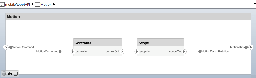
Create Model Reference
Model references can help you organize large models hierarchically and define architectures or behaviors once that you can then reuse. When a component references another model, any existing ports on the component are removed, and ports that exist on the referenced model appear on the component.
Create a new System Composer model. Convert the Controller component into a reference component to reference the new model. To add ports on the Controller component, you must update the referenced model mobileMotion.
referenceModel = systemcomposer.createModel("mobileMotion");
referenceArch = referenceModel.Architecture;
newComponents = addComponent(referenceArch,"Gyroscope");
referenceModel.save

linkToModel(motionController,"mobileMotion");

Save the models.
referenceModel.save
model.save
Make Variant Component
You can convert the Motion component to a variant component by using the makeVariant function. The original component is embedded within a variant component as one of the available variant choices. You can design other variant choices within the variant component and toggle the active choice. Variant components allow you to choose behavioral designs programmatically in an architecture model to perform trade studies and analysis.
[variantComp,choice1] = makeVariant(componentMotion);
Add a variant choice named MotionAlt. The second argument defines the name, and the third argument defines the label. The label identifies the choice. The active choice is controlled by the label.
choice2 = addChoice(variantComp,{'MotionAlt'},{'MotionAlt'});Create the necessary ports on MotionAlt.
motionAltPorts = addPort(choice2.Architecture,{'MotionCommand','MotionData'},{'in','out'});Make MotionAlt the active variant.
setActiveChoice(variantComp,"MotionAlt")Arrange the layout by pressıng Ctrl+Shift+A, or use this command.
Simulink.BlockDiagram.arrangeSystem("mobileRobotAPI/Motion");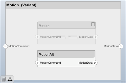
Save the model.
model.save
Clean Up
To remove generated artifacts before you run this example again, run this script.
cleanUpArtifacts
More About
Version History
Introduced in R2019a
See Also
Functions
iterate|current|getQualifiedName|lookup|systemcomposer.createModel|systemcomposer.loadModel|systemcomposer.openModel|open|save|close|createArchitectureModel|createArchitectureSubsystem|linkToModel|inlineComponent|addComponent|getComponent|addPort|getPort|setName|getSubElement|getPortElement|getConnectorTo|connect|setMaskImage|IsAdapterComponent|addAdapter|addInput|getInput|connectTo|updatePosition|addMapping|removeMapping|smartConnect|getUnconnectedPorts|getSmartConnectPolicy|setSmartConnectPolicy|destroy
Objects
systemcomposer.arch.Element|systemcomposer.arch.Architecture|systemcomposer.arch.Component|systemcomposer.arch.Adapter|systemcomposer.arch.ArchitecturePort|systemcomposer.arch.PortElement|systemcomposer.arch.Connector|systemcomposer.arch.PhysicalConnector