Create Parent and Child Operating Modes in State Transition Tables
You can create more complex logic in a state transition table by creating child states that can activate only when their parent state is active. In the States column, states are indented under their parent states.
Child states have their own default transitions. When the parent state becomes active, the child state connected to the default transition also becomes active. Then, the table transitions between the child states. When the parent state deactivates, the child states also deactivate.
In this example, you use child states to model the variable charging rates in a rechargeable battery system.
Open Model
The sfGetStartedBatteryTable model represents the control logic for a rechargeable battery system. To build the model, follow the instructions in the previous steps of the tutorial.
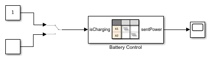
The State Transition Table block Battery Control contains the control logic for the system. To determine whether the battery charges or discharges, the table receives a Manual Switch block as an input.
To view the table, double-click the State Transition Table block.
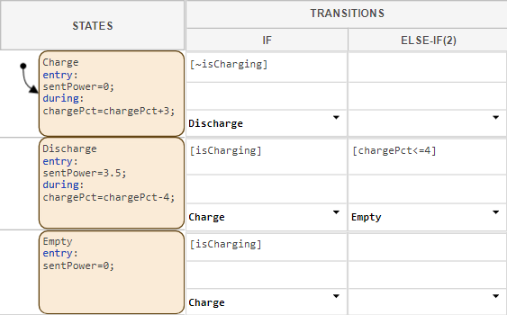
The states Charge, Discharge, and Empty represent the operating modes of the battery system. The table uses these data:
isCharging: An input that determines whether the battery should charge or discharge.chargePct: A local data that represents the charge level of the battery as a percent of total charge.sentPower: An output that determines how many watts of power the battery sends at any given time.
Add Child States to Model Hierarchy
Currently, the battery system continues charging when full. To prevent the battery from charging beyond full, add states representing fast, intermediate, and full charging modes.
Point to the
Chargestate and click Add child state. Name the child stateFastCharge.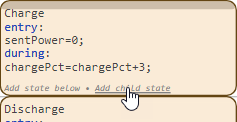
Add two additional child states named
SlowChargeandFull.
Note
To hide child states, on the left side of the parent state, click the Hide child states button
 . To show hidden states, click the Show
child states button
. To show hidden states, click the Show
child states button  .
.
Add transitions that allow the table to move between the charging modes.
Create a transition from
FastChargetoSlowChargethat executes when the battery charge is greater than 80%.Create a transition from
SlowChargetoFullthat executes when the battery charge is greater than or equal to 100%.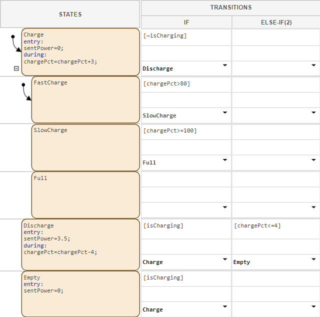
Add state actions that increase the battery charge.
In the
Chargestate, remove the existingduringactions.In the
FastChargestate, add aduringaction that increases the battery charge by 4%. In theSlowChargestate, add aduringaction that increases the battery charge by 1%.
Simulate Model
Observe how the table transitions between child states.
To slow the pace of the simulation, in the Simulation tab, click Run > Simulation Pacing. Then, select Enable pacing to slow down simulation.
In the top model, confirm that the Manual Switch block connects to the Constant block with a value of
1.In the Simulation tab, click Run to simulate the model. In the first step, the
ChargeandFastChargestates both activate. Aschargeincreases, the table transitions to child statesSlowChargeandFull.
The battery model now stops charging when the battery charge is 100%. In the next step of the tutorial, you add a non-rechargeable emergency battery that maintains essential functions if the main battery runs out of power. To model the simultaneous operation of the batteries, you use parallel states.