Low-Pass Filter (Variable Time Constant, Discrete or Continuous)
Discrete-time or continuous-time low-pass filter with external variable time constant
Since R2026a

Libraries:
Simscape /
Electrical /
Control /
General Control
Description
The Low-Pass Filter (Variable Time Constant, Discrete or Continuous) block implements a low-pass filter with an external time constant input and in conformance with IEEE 421.5-2016 [1]. In the standard, the filter is referred to as a Simple Time Constant.
You can switch between continuous and discrete implementations of the integrator using the Sample time parameter.
For a version of this block with the time constant as a parameter, see the Low-Pass Filter (Discrete or Continuous) block.
Equations
To configure the filter for continuous time, set the Sample
time parameter to 0. This representation is
equivalent to the continuous transfer function:
where:
K is the filter gain.
T is the filter time constant.
From the preceding transfer function, the filter defining equations are:
where:
u is filter input.
x is filter state.
y is filter output.
t is simulation time.
u0 is the initial input to the block.
To configure the filter for discrete time, set the Sample
time parameter to a positive, nonzero value. To inherit the
sample time from an upstream block, set the Sample time
parameter to -1. The discrete representation is equivalent to
the transfer function:
where:
K is the filter gain.
T is the filter time constant.
Ts is the filter sample time.
From the discrete transfer function, the filter equations are defined using the forward Euler method:
where:
u is the filter input.
x is the filter state.
y is the filter output.
n is the simulation time step.
u0 is the initial input to the block.
Initial Conditions
To specify the initial conditions of this block, set the Initialization parameter to:
Inherited from block input— The block sets the state and output initial conditions to the initial input.Specify as parameter— The block sets the state initial condition to the value of the Initial state parameter.
Limiting the Integral
Set the Upper saturation limit and Lower saturation limit parameters to use the anti-windup saturation method.
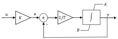
The anti-windup method limits the integrator state between the lower saturation limit A and upper saturation limit B:
Because the state is limited, the output can respond immediately to a reversal of the input sign when the integral is saturated. This block diagram depicts the implementation of the anti-windup saturation method in the filter.
This block does not provide a windup saturation method. To use the windup
saturation method, set the Upper saturation limit parameter to
inf, the Lower saturation limit
parameter to -inf, and attach a saturation block
to the output.
Bypass Filter Dynamics
To ignore the dynamics of the filter, set the time constant input to a value smaller than or equal to the sample time. When bypassed, the block feeds the gain-scaled input directly to the output:
In the continuous case, the sample time and time constant must both be zero.
Ports
Input
Output
Parameters
References
[1] IEEE® Standard 421.5-1992. "IEEE Recommended Practice for Excitation System Models for Power System Stability Studies." August 1992. https://ieeexplore.ieee.org/document/7553421.
Extended Capabilities
Version History
Introduced in R2026a