順運動学と逆運動学の 5 節ロボットでの実行
この例では、KinematicsSolverオブジェクトを使用して、5 節ロボット機構で順運動学 (FK) と逆運動学 (IK) を実行する方法を示しています。まず、例では FK 解析を実施して 5 節ロボットについて特異点のないワークスペースを計算する方法を示します。次に、IK 解析を実施して、そのワークスペース内のエンドエフェクタの軌跡に対応するモーター角を計算する方法を示します。
5 節ロボットは、5 節平面マニピュレーターとも呼ばれる、2 自由度のパラレル メカニズムです。この例では、ロボットに等長のリンクが 4 つあり、互いに衝突しないようになっています。ロボットは 2 つのステッピング モーターを使用して近位リンクを駆動し、ペンを動かします。

5 節ロボットにはコンフィギュレーション空間の領域として --、-+、++、+- の 4 つがあります。図に示すとおり、それぞれの符号は、対応する近位リンクと遠位リンク間のオフセット角の符号を表します。能動回転ジョイント a および b はモーターによって直接制御され、受動回転ジョイント c および d は近位リンクと遠位リンクを接続します。
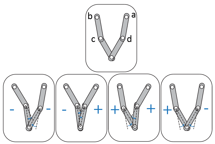
アームの一方または両方が完全に伸びている構成では、エンドエフェクタの自由度が少なくとも 1 低下します。このような構成は運動学的特異点に対応しており、ロボットが領域間で遷移するときに発生します。FK 解析で運動学的特異点を回避するため、この例では +- 領域での 5 節ロボット ワークスペースのみを調べます。
5 節ロボットでの順運動学の実行
この節では、FK 解析を実施して、一連のモーター角に対応するペンについて特異点のないワークスペースを計算する方法を説明します。具体的には、この例ではロボットの能動ジョイント角をターゲット変数として割り当て、ペンの x 座標と y 座標を出力変数として割り当てます。また、この例では受動ジョイントを初期推定変数として割り当てますが、これらは解に +- 領域へのバイアスをつけるために使用されます。
1. FK 解析を実施するには、まず 5 節ロボットのモデルをメモリに読み込み、モデルの KinematicsSolver オブジェクト (fk) を作成します。
mdl = "FiveBar";
load_system(mdl);
fk = simscape.multibody.KinematicsSolver(mdl);
2. ロボットのペン、ワールド座標系、能動ジョイント、受動ジョイント間の関係の指定と調査を行うには、ワールド座標系に対し、ペンの位置に対応する座標系変数を作成する必要があります。ジョイント変数はオブジェクトの構成時に自動的に作成されるため、作成する必要はありません。
ペンに対する 3 つの変換座標系変数のグループを fk に追加します。ワールド座標系を base として、またペンの先端の座標系を follower として指定します。座標系変数グループに Pen という名前を付けます。
base = mdl + "/World Frame/W";
follower = mdl + "/Five Bar Robot/Pen/Pen/Tip";
addFrameVariables(fk,"Pen","Translation", base, follower);
3. 能動ジョイントの位置ベースのジョイント変数 (j5.Rz.q および j4.Rz.q) をターゲットとして割り当てます。位置ベースのジョイント変数の ID を検索するには、オブジェクト関数 jointPositionVariables を使用します。
jointPositionVariables(fk)
ans=5×4 table
       ID           JointType                             BlockPath                          Unit
    _________    ________________    ____________________________________________________    _____

    "j1.Rz.q"    "Revolute Joint"    "FiveBar/Five Bar Robot/Passive_Joint_c"                "deg"
    "j2.Rz.q"    "Revolute Joint"    "FiveBar/Five Bar Robot/Passive_Joint_d"                "deg"
    "j3.Rz.q"    "Revolute Joint"    "FiveBar/Five Bar Robot/Passive_Joint_e"                "deg"
    "j4.Rz.q"    "Revolute Joint"    "FiveBar/Five Bar Robot/Step_Motor_a/Active_Joint_a"    "deg"
    "j5.Rz.q"    "Revolute Joint"    "FiveBar/Five Bar Robot/Step_Motor_b/Active_Joint_b"    "deg"
targetIDs = ["j5.Rz.q";"j4.Rz.q"];
addTargetVariables(fk,targetIDs);
4. 以下の変数を出力として割り当てます。
ペンの並進の x および y 成分 (
Pen.Translation.xおよびPen.Translation.y)受動ジョイントのジョイント変数 (
j1.Rz.qおよびj2.Rz.q)
座標系変数の ID を検索するには、オブジェクト関数 frameVariables を使用します。
frameVariables(fk)
ans=3×4 table
            ID                      Base                            Follower                  Unit
    ___________________    _______________________    ____________________________________    ____

    "Pen.Translation.x"    "FiveBar/World Frame/W"    "FiveBar/Five Bar Robot/Pen/Pen/Tip"    "m"
    "Pen.Translation.y"    "FiveBar/World Frame/W"    "FiveBar/Five Bar Robot/Pen/Pen/Tip"    "m"
    "Pen.Translation.z"    "FiveBar/World Frame/W"    "FiveBar/Five Bar Robot/Pen/Pen/Tip"    "m"
outputIDs = ["Pen.Translation.x";"Pen.Translation.y";"j1.Rz.q";"j2.Rz.q"];
addOutputVariables(fk,outputIDs);
5. 受動ジョイントのジョイント変数 (j1.Rz.q および j2.Rz.q) を推定として割り当てます。
guessIDs = ["j1.Rz.q";"j2.Rz.q"];
addInitialGuessVariables(fk,guessIDs);
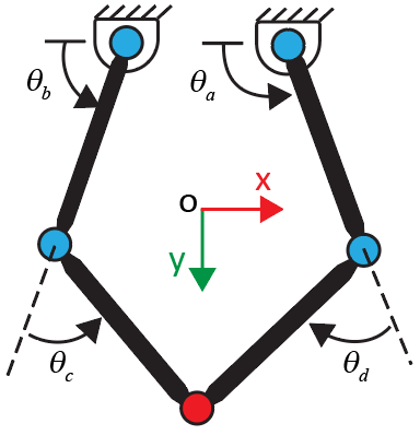
6. 図は 5 節ロボットのスケッチです。能動ジョイントの角度は および 、受動ジョイントの角度は および です。入れ子の for ループを使用して、[95, 150] 度および [30, 85] 度の範囲でそれぞれ変化する能動ジョイントの角度のセットに対し、ペンのワークスペースを計算します。ロボットが +- 領域内にあることを確実するには、推定変数 (j1.Rz.q and j2.Rz.q) の初期値として [50 -50] 度を使用し、その後、推定変数の最新値を使用して次の FK の解を導きます。
guesses = [50 -50]; % Initial guesses for theta_c and theta_d
index = 1;

% Generate angles for theta_a and theta_b
theta_a = linspace(95,150,31);
theta_b = linspace(30,85,31);

% Allocate memory for output data
ik_data = zeros(length(theta_a)*length(theta_b),length(outputIDs));

% Calculate the robot's workspace for the given theta_a and theta_b
for i = 1:length(theta_a)
    for j = 1:length(theta_b)
        targets = [theta_b(j),theta_a(i)];
        [outputVec,statusFlag] = solve(fk,targets,guesses);
        if statusFlag == 1 % Save a solution if its statusFlag is 1
            ik_data(index,1:length(outputIDs)) = outputVec;
            index = index + 1;
            guesses = [outputVec(3),outputVec(4)]; % Update next guess with last solution
        end
    end
end
7. 受動ジョイントの角度をプロットして、5 節ロボットが +- 領域内にあるかどうかを確かめます。ロボットが +- 領域内にある場合、 の値は常に正、 の値は常に負となります。
figure
plot(ik_data(1:index-1,3),"b","LineWidth",2); % Note that the total number of the solutions that satisfy statusFlag equals to index-1;
hold on
plot(ik_data(1:index-1,4),"k","LineWidth",2);
hold off


title("Passive Joint Angles")
xlabel("Index")
ylabel("Angle (Degrees)")
legend("Joint c","Joint d")
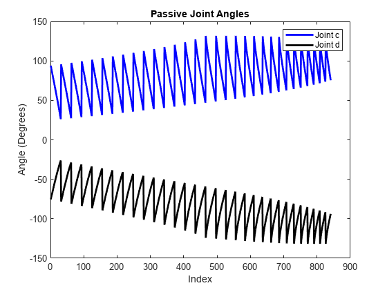
プロットから、5 節ロボットは +- 領域内にあることがわかります。さらに、 と の値が 0 から離れているため、計算されたワークスペースに特異点はありません。
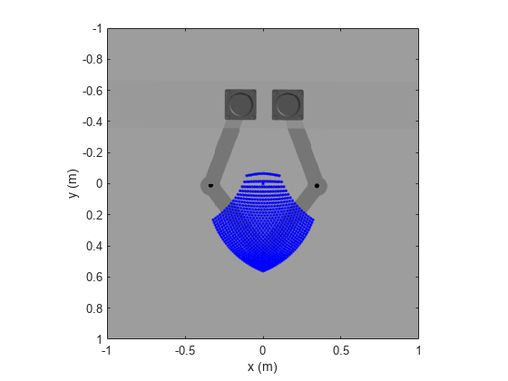
8. ワークスペースのデータを 5 節ロボットのイメージにプロットします。
% Plot the image of the five-bar robot
figure
x = [-1 1];
y = [1 -1];
C = imread("TopViewFiveBarRobot.png");
image(x,y,C)

hold on

% Plot the calculated workspace as blue dots
plot(ik_data(:,1),ik_data(:,2),"b.")
ylabel("y (m)")
xlabel("x (m)")
axis equal
axis([-1 1 -1 1]);
hold off
5 節ロボットでの逆運動学の実行
この節の例では、IK 解析を実施して、エンドエフェクタの軌跡に対応するモーター角を計算する方法を説明します。具体的には、この例ではペンの並進の x および y 成分をターゲット変数として割り当て、モーター角を出力変数として割り当てます。そのうえで、ペンの軌跡に対するモーター角を計算します。ロボットが +- 領域にあるよう確保するには、能動ジョイントと受動ジョイントの角度を推定として使用して IK の解にバイアスをつけます。この節を実行する前に、FK の節を実行する必要があることに注意してください。
1. 前に計算したワークスペース内で、円形のエンドエフェクタの軌跡を定義します。IK 解析用に円の座標を保存します。
figure
% Plot the calculated workspace as blue dots on the image of the five-bar robot
image(x,y,C)
hold on
plot(ik_data(:,1),ik_data(:,2),"b.")

% Specify the center and radius of the circle
center_x = 0; % m
center_y = 0.3; % m
radius = 0.15; % m
th = 0:pi/50:2*pi; % radians

% Save the x and y coordinates of the circle for the IK analyses
coordinates_x = radius * cos(th) + center_x;
coordinates_y = radius * sin(th) + center_y;

% Plot the circle
plot(coordinates_x,coordinates_y,"r","LineWidth",2)
axis equal
axis([-1 1 -1 1]);
ylabel("Length (m)")
xlabel("Width (m)")
hold off
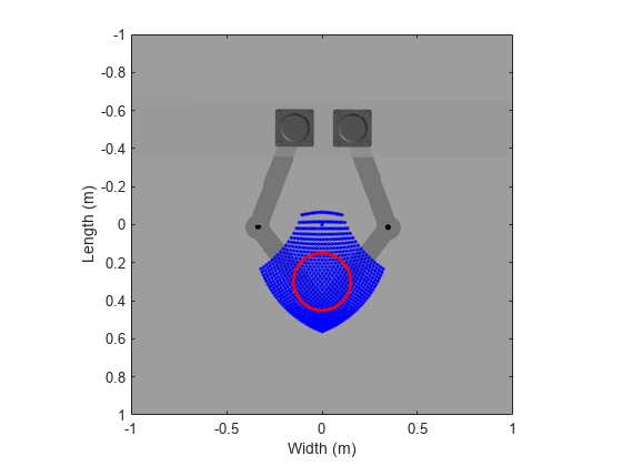
2. IK 解析を実施するには、まずモデルの KinematicsSolver オブジェクト (ik) を作成します。
ik = simscape.multibody.KinematicsSolver(mdl);
3. ワールド座標系に対してペンの位置の座標系変数を作成し、それらをオブジェクト (ik) に追加します。FK の節の base 変数と follower 変数を再利用するこが可能です。
addFrameVariables(ik, "Pen","Translation", base, follower);
4. ペンの並進の x および y 成分 (Pen.Translation.x および Pen.Translation.y) に対応する変数を、ターゲットとして割り当てます。座標系変数の ID を検索するには、オブジェクト関数 frameVariables を使用します。
frameVariables(ik)
ans=3×4 table
            ID                      Base                            Follower                  Unit
    ___________________    _______________________    ____________________________________    ____

    "Pen.Translation.x"    "FiveBar/World Frame/W"    "FiveBar/Five Bar Robot/Pen/Pen/Tip"    "m"
    "Pen.Translation.y"    "FiveBar/World Frame/W"    "FiveBar/Five Bar Robot/Pen/Pen/Tip"    "m"
    "Pen.Translation.z"    "FiveBar/World Frame/W"    "FiveBar/Five Bar Robot/Pen/Pen/Tip"    "m"
targetIds = ["Pen.Translation.x";"Pen.Translation.y"];
addTargetVariables(ik,targetIds);
5. 以下の変数を出力として割り当てます。
能動ジョイントの位置ベースのジョイント変数 (
j5.Rz.qおよびj4.Rz.q)受動ジョイントの位置ベースのジョイント変数 (
j1.Rz.qおよびj2.Rz.q)
位置ベースのジョイント変数の ID を検索するには、オブジェクト関数 jointPositionVariables を使用します。
jointPositionVariables(ik)
ans=5×4 table
       ID           JointType                             BlockPath                          Unit
    _________    ________________    ____________________________________________________    _____

    "j1.Rz.q"    "Revolute Joint"    "FiveBar/Five Bar Robot/Passive_Joint_c"                "deg"
    "j2.Rz.q"    "Revolute Joint"    "FiveBar/Five Bar Robot/Passive_Joint_d"                "deg"
    "j3.Rz.q"    "Revolute Joint"    "FiveBar/Five Bar Robot/Passive_Joint_e"                "deg"
    "j4.Rz.q"    "Revolute Joint"    "FiveBar/Five Bar Robot/Step_Motor_a/Active_Joint_a"    "deg"
    "j5.Rz.q"    "Revolute Joint"    "FiveBar/Five Bar Robot/Step_Motor_b/Active_Joint_b"    "deg"
outputIds = ["j5.Rz.q";"j4.Rz.q";"j1.Rz.q";"j2.Rz.q"];
addOutputVariables(ik,outputIds);
6. for ループを使用して IK 解析を実装します。具体的には、for ループを使用して、事前定義された軌跡の座標をペンに割り当て、対応するモーター角を計算します。
N = length(coordinates_x); % Number of points on trajectory
index_in_ik = 1;
ik_data = zeros(N,length(outputIds)); % Allocate memory for the variable

for ind = 1:N
    targets = [coordinates_x(ind), coordinates_y(ind)]; % Use the x and y coordinates of the predefined circle for the inverse kinematics problem
    [outputVec_ik,statusFlag_ik] = solve(ik,targets);
    if statusFlag_ik == 1
        ik_data(index_in_ik,1:length(outputIds)) = outputVec_ik; % save the output data
        index_in_ik = index_in_ik+1;
    else
        error("Did not hit targets");
    end
end
closeViewer(ik);
7. ロボットの受動ジョイントをプロットして、ロボットが +- 領域内にあるかどうかを確認します。
% Plot the angles of the passive joints
figure
plot(ik_data(:,3),"b","LineWidth",2);
hold on
plot(ik_data(:,4),"k","LineWidth",2);
hold off
title("Passive Joint Angles")
xlabel("Point")
ylabel("Angle (Degrees)")
legend("Joint c","Joint d")
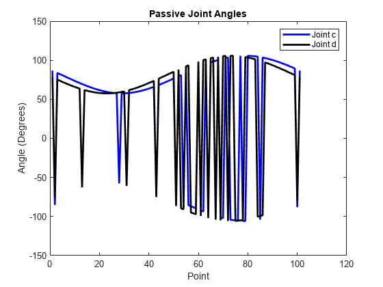
プロットから、ロボットは常には +- 領域内にないことがわかります。
8. すべての解が +- 領域に必ず留まるようにするため、受動ジョイントのジョイント変数 (j1.Rz.q および j2.Rz.q) と、能動ジョイントのジョイント変数 (j5.Rz.q および j4.Rz.q) を推定として割り当て、IK の解にバイアスをつけます。
guessIds = ["j1.Rz.q";"j2.Rz.q";"j5.Rz.q";"j4.Rz.q"];
addInitialGuessVariables(ik,guessIds);
推定変数の初期値として [50 -50 45 135] 度を使用し、推定変数の最新値を使用して次の IK の解を導きます。
guesses = [50 -50 45 135]; % Assign initial guesses for passive and active joints
N = length(coordinates_x);
index_in_ik = 1;
ik_data = zeros(N,length(outputIds)); % Allocate memory for the variable
for ind = 1:N
    targets = [coordinates_x(ind), coordinates_y(ind)]; % Use the x and y coordinates of the prescribed circle for the inverse kinematics problem
    [outputVec_ik,statusFlag_ik] = solve(ik,targets, guesses);
    if statusFlag_ik == 1
        ik_data(index_in_ik,1:length(outputIds)) = outputVec_ik; % Save the rotations of the motors
        index_in_ik=index_in_ik+1;
        guesses = [outputVec_ik(3) outputVec_ik(4) outputVec_ik(1) outputVec_ik(2)]; % Update next guess with last solution
    else
        error("Did not hit targets");
    end
end
closeViewer(ik);
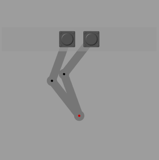
プロットでは、受動ジョイント角が常にゼロから十分離れており、常に +- 領域にあることが示されています。したがって、このモーター角のセットは、運動学的特異点を経由せずに円形軌跡に沿って滑らかに動くエンドエフェクタに対応します。
% Plot the angles of the passive joints
figure
plot(ik_data(:,3),"b","LineWidth",2);
hold on
plot(ik_data(:,4),"k","LineWidth",2);
hold off
title("Passive Joint Angles")
xlabel("Index")
ylabel("Angle (Degrees)")
legend("Joint c","Joint d")
参考
KinematicsSolver | frameVariables | initialGuessVariables | jointPositionVariables | outputVariables | targetVariables | addFrameVariables | addInitialGuessVariables | addOutputVariables | addTargetVariables | solve | viewSolution | closeViewer