Main Content

simscape.multibody.RigidBody Class

Namespace: simscape.multibody
Superclasses: simscape.multibody.Component

Construct rigid body

Since R2022a

Description

Use an object of the simscape.multibody.RigidBody class to construct a rigid body. A RigidBody object is a hierarchical container and has a tree structure composed of rigidly connected frames and component objects.

By default, a newly created RigidBody object contains only one frame called reference. The reference frame serves as the root of the tree structure. You must explicitly add frames or component objects to a RigidBody object, and the new frame or component object must be rigidly connected to the tree structure of the RigidBody object. Note that the name of every frame or component object must be unique among the frames and objects at the same hierarchical level of the RigidBody object.

In a larger system, to connect to other frames or component objects, a RigidBody object must have at least one connector. By default, a newly created RigidBody object has zero connectors, and adding frames or component objects to a RigidBody object does not automatically create connectors. To add a connector, use the addConnector method. Note that you can add connectors only to the frames at the top level of the RigidBody object, and each frame can only have one connector.

See More About section for more information about the RigidBody class.

The simscape.multibody.RigidBody class is a handle class.

Class Attributes

Sealed
true
ConstructOnLoad
true
HandleCompatible
true
RestrictsSubclassing
true

For information on class attributes, see Class Attributes.

Creation

Description

rb = simscape.multibody.RigidBody creates a simscape.multibody.RigidBody object.

example

Properties

expand all

Names of the component objects at the top level of a simscape.multibody.RigidBody object, returned as a string array.

Example: "sphere"

Attributes:

GetAccess
public
SetAccess
Restricts access
NonCopyable
true
Transient
true

Names of the frames at the top level of a simscape.multibody.RigidBody object, returned as a string array.

Example: "reference"

Attributes:

GetAccess
public
SetAccess
Restricts access
NonCopyable
true
Transient
true

Methods

expand all

Examples

collapse all

This example shows how to create a link that has a rectangular shape with two end frames.

To avoid typing the namespace name for the classes, you can use the import function.

import simscape.Value simscape.op.* simscape.multibody.*;
  • Create a simscape.multibody.RigidBody object to construct a rigid body named link. By default, the newly created object has one frame.

link = RigidBody
link = 
  RigidBody:

  No connectors.

  Frames:

  Frame        Parent  Source  Connector?
  ___________  ______  ______  __________

  "reference"  --      --      No        

  No components.

  RigidBody with properties:

         FrameNames: "reference"
     ComponentNames: [0x1 string]
        DoVisualize: 1
    FrameConnectors: [0x1 string]

  • To create the body of the link, you can use the simscape.multibody.Solid class. The body has a rectangular shape whose length, width, and height are 10 cm, 1 cm, and 1 cm, respectively. The length is in the x-direction of the local reference frame. The body is made of aluminum and has the red color.

body = Solid(Brick(Value([10 1 1],"cm")),UniformDensity(Value(2700,"kg/m^3")),SimpleVisualProperties([1 0 0]));
  • To add the body to the reference frame of the link object, use the addComponent method.

addComponent(link,"Body","reference",body);
  • To add a frame to each end of the link, you can use the addFrame method. The frames are named as neg_end and pos_end, respectively.

length = Value(10,"cm");
offset = length/2;
addFrame(link,"neg_end","reference",RigidTransform(StandardAxisTranslation(offset,Axis.NegX)));
addFrame(link,"pos_end","reference",RigidTransform(StandardAxisTranslation(offset,Axis.PosX)));
  • To be able to connect the link to other bodies or joints, the link needs to have connectors. To add connectors to the end frames, you can use the addConnector method.

addConnector(link,"neg_end");
addConnector(link,"pos_end");
  • To see the components in the link object, you can type:

link
link = 
  RigidBody:

  Connectors:

  Name       Type 
  _________  _____

  "neg_end"  Frame
  "pos_end"  Frame

  Frames:

  Frame        Parent       Source  Connector?
  ___________  ___________  ______  __________

  "reference"  --           --      No        
  "neg_end"    "reference"  Trans   Yes       
  "pos_end"    "reference"  Trans   Yes       

  Components:

  Name    Type   Frame        Connector
  ______  _____  ___________  _________

  "Body"  Solid  "reference"  "R"      

  RigidBody with properties:

         FrameNames: [3x1 string]
     ComponentNames: "Body"
        DoVisualize: 1
    FrameConnectors: [2x1 string]

This example shows how to add a frame, solid, and sub-rigid body to a rigid body.

  • To avoid typing the namespace name for the classes, you can use the import function.

import simscape.multibody.*;
  • Create a simscape.multibody.RigidBody object named rb. The rb object has one frame called reference and no connectors.

rb = RigidBody
rb = 
  RigidBody:

  No connectors.

  Frames:

  Frame        Parent  Source  Connector?
  ___________  ______  ______  __________

  "reference"  --      --      No        

  No components.

  RigidBody with properties:

         FrameNames: "reference"
     ComponentNames: [0x1 string]
        DoVisualize: 1
    FrameConnectors: [0x1 string]

  • To add frames to the reference frame, create and add frames to a rigid transform object. First, create a simscape.multibody.RigidTransform object named rt. The rt object represents a translation along the positive y-axis of the base frame. The distance of the translation is 50 cm.

rt = RigidTransform(StandardAxisTranslation(simscape.Value(50,"cm"),Axis.PosY));
  • Then, use the addFrame method to add two frames, fa and fb, to the reference frame through the rt object.

addFrame(rb,"fa","reference",rt);
addFrame(rb,"fb","reference",rt);
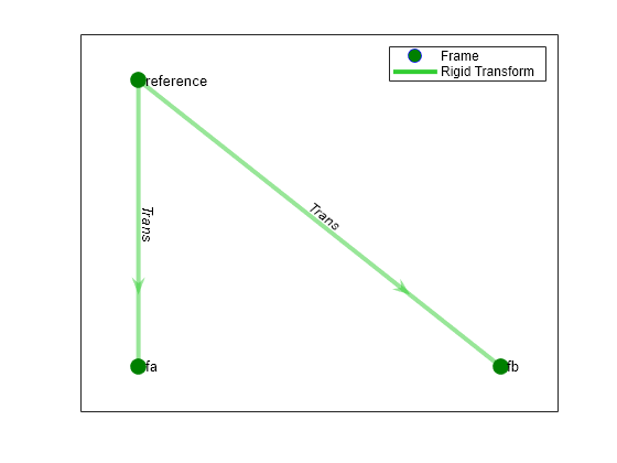
  • You can view the tree structure of the rb object by using the plotStructure method.

plotStructure(rb);

Figure contains an axes object. The axes object contains 3 objects of type line, graphplot. One or more of the lines displays its values using only markers These objects represent Frame, Rigid Transform.

The green vertexes represent the frames, and the green lines represent the rigid transforms between the frames. The arrows indicate the orientations of the rigid transforms. By default, a rigid transform maps vectors from the new frame to the parent frame.

  • Add a simscape.multibody.Solid object to the rb object. First, create a simscape.multibody.Solid object called sphere. The sphere object represents a solid with a spherical shape. The sphere has a radius of 50 cm.

sphere = Solid(Sphere(simscape.Value(50,"cm")));

Then, use the addComponent method to add the sphere object to the fa frame. By default, a Solid object has one connector that you can connect to the rb object.

addComponent(rb,"sphere","fa",sphere);

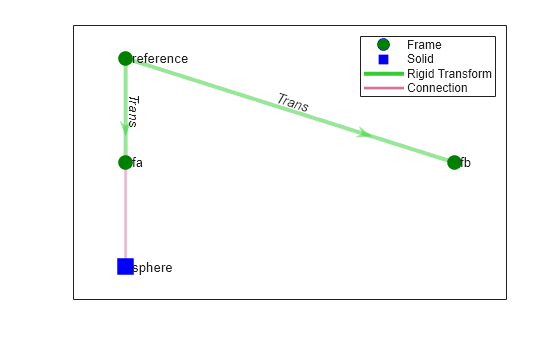
Use the plotStructure method to show the tree structure of the rb object in a new figure.

figure
plotStructure(rb);

Figure contains an axes object. The axes object contains 5 objects of type line, graphplot. One or more of the lines displays its values using only markers These objects represent Frame, Solid, Rigid Transform, Connection.

The blue vertex represents the sphere object, and the pink link indicates the connection between the fa frame and the sphere object.

  • Add a RigidBody object to the rb object as a subbody. Create an empty RigidBody object called subrb and add two new frames, f1 and f2, to the subrb object through the rt object.

subrb = RigidBody;
addFrame(subrb,"f1","reference",rt);
addFrame(subrb,"f2","reference",rt);

Because the subrb object has zero connectors, you must add at least one connector to the object. Use the addConnector method to add a connector to the f1 frame of the subrb object. The connector and frame have the same name.

addConnector(subrb,"f1");

Use the addComponent method to attach the subrb object to the fb frame through the f1 connector.

addComponent(rb,"subrb","fb",subrb,"f1");

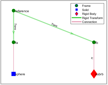
Use the plotStructure method to show the tree structure of the rb object in a new figure.

figure
plotStructure(rb);

Figure contains an axes object. The axes object contains 6 objects of type line, graphplot. One or more of the lines displays its values using only markers These objects represent Frame, Solid, Rigid Body, Rigid Transform, Connection.

The red vertex represents the subrb object, and the pink line indicates the connection between the fb frame and the f1 connector of the subrb object.

More About

expand all

Version History

Introduced in R2022a