Test Objective
Define custom objectives that signals must satisfy in test cases
Libraries:
Simulink Design Verifier /
Objectives and Constraints
Description
When operating in test generation mode, the Simulink® Design Verifier™ software produces test cases that satisfy the specified criteria (see Workflow for Test Generation). In this mode, you can use Test Objective blocks to define custom test objectives for signals in your model. The Values parameter lets you specify values that a signal must achieve for at least one time step during a test case simulation. The block applies the specified Values parameter to its input signal, and the Simulink Design Verifier software attempts to produce test cases that satisfy the objective.
The block's parameter dialog box also allows you to
Enable or disable the objective.
Specify that the block should display its Values parameter in the Simulink editor.
Specify that the block should display its output port.
Note
The Simulink and Simulink Coder™ software ignore the Test Objective block during model simulation and code generation, respectively. The Simulink Design Verifier software uses the Test Objective block only when generating test cases for a model.
Examples
This example shows the use of two custom Test Objective blocks. The block "True" forces the output signal to be 2. The block "Edge" inside "Masked Objective" specifies that the output signal transition from 2 to 1.
open_system('sldvdemo_debounce_testobjblks');

Ports
Input
Parameters
If selected (the default), Simulink Design Verifier software uses the block when generating tests for a model. Clearing this option disables the block, that is, causes the Simulink Design Verifier software to behave as if the Test Objective block did not exist. If this option is not selected, the block appears grayed out in the Simulink Editor.
Specifying Test Objectives
Use the Values parameter to define custom objectives that signals must satisfy in test cases. Specify any combination of scalars and intervals in the form of a MATLAB® cell array. For information about cell arrays, see Cell Arrays.
Tip
If the Values parameter specifies only one scalar value, you do not need to enter it in the form of a MATLAB cell array.
Scalar values each comprise a single cell in the array, for example:
{0, 5}A closed interval comprises a two-element vector as a cell in the array, where each element specifies an interval endpoint:
{[1, 2]}Alternatively, you can specify scalar values using the
Sldv.Point constructor, which accepts a single
value as its argument. You can specify intervals using the
Sldv.Interval constructor, which requires two
input arguments, i.e., a lower bound and an upper bound for the
interval. Optionally, you can provide one of the following values as a
third input argument that specifies inclusion or exclusion of the
interval endpoints:
'()'— Defines an open interval.'[]'— Defines a closed interval.'(]'— Defines a left-open interval.'[)'— Defines a right-open interval.
Note
By default, Sldv.Interval considers an interval
to be closed if you omit its third input argument.
As an example, the Values parameter
{0, [1, 3]}specifies:
0— a scalar[1, 3]— a closed interval
The Values parameter
{Sldv.Interval(0, 1, '[)'), Sldv.Point(1)}specifies:
Sldv.Interval(0, 1, '[)')— the right-open interval [0, 1)Sldv.Point(1)— a scalar
Logical Behavior of Specifications
If you specify multiple scalars and intervals for a Test Objective block, the Simulink Design Verifier software combines them using a logical OR operation when generating test cases. Consequently, the software considers the entire test objective to be satisfied if any single scalar or interval is satisfied.
Within a single scalar or interval, a test objective is generated with a logical AND operation. In this case, all signals must satisfy the constraints in order for the input to satisfy the objective.
For example, consider a two-dimensional open interval:
Sldv.Interval([-5 -5],[5 2],'()')
The zero vector [0 0] satisfies the objective
because the zero elements are within the intervals -5
to 5 and -5 to
2.
The vector [0 3] does not satisfy the objective
because the second element 3 falls outside the interval
-5 to 2.
Specify whether the block displays the contents of its Values parameter in the Simulink Editor.
If selected, the block displays its output port, allowing its input signal to pass through as the block output. If not selected, the block hides its output port and terminates the input signal.
Example: The following graphics illustrate the appearance of the block in each case.
Pass through style (show Outport): Selected
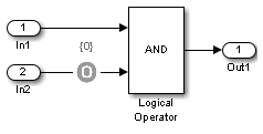
Pass through style (show Outport): Deselected

Extended Capabilities
Version History
Introduced in R2007a