Share Port Constraints Across Multiple Masked Blocks
You can create a port constraint in an XML file and share it across masks of different blocks in the same model or different models.The XML file must be available on the MATLAB® path.
Port constraints enable you to validate compile-time signal attributes on the input and output ports of a masked block without having to write validation code. Sharing of port constraints eliminates the need to repeatedly update multiple blocks, making maintenance and management of constraints more efficient. When you define a shared constraint in an XML file, you can compare the constraint definition with a previous version.
Explore Model
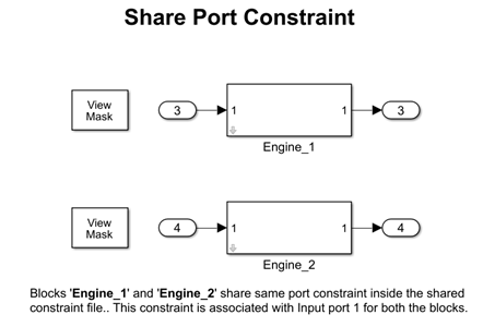
In the model slexMaskPortConstraint, refer to the Subsystem blocks, Engine_1 and Engine_2. The shared port constraint ScalarInt8SharedConstraint is saved in the XML file sharedPortChecks.xml. The constraint validates whether the signals at input ports at index 1 of the Subsystem blocks are int8, scalar, and real at compile time.
Create Shared Port Constraint
To create the port constraint ScalarInt8SharedConstraint in an XML file:
1. Create a Subsystem block Engine_1 with one input port, In1, and one output port, Out1.
2. Create a mask on the block.
3. In the Mask Editor, create a check box parameter named BatteryCheck. You will use this parameter to add the parameter condition to the constraint in later steps.
4. In the Constraints tab, click New, and enter the name of the XML file as sharedPortChecks.
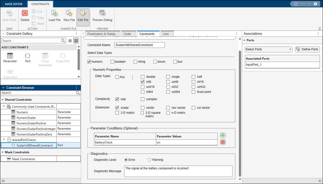
5. In the Constraint Gallery pane, create a port constraint by clicking Port. Specify Constraint as ScalarInt8SharedConstraint. Set Data Type as int8, Complexity as real, and Dimension as scalar.
6. To add parameter conditions, in the Parameter Conditions section, click the plus button. Set Parameter Name to BatteryCheck, and set the value to on. The signal at the port is validated only when the parameter condition is satisfied.
7. In the Diagnostics section, select Error for Diagnostic Level. In the Diagnostic Message box, enter a message for the software to display if the parameter condition validation fails.
8. Create a port identifier for the input port with index 1. In the Associations pane, click Define Ports. In the Port Identifiers section, click Add. Specify Name as InputPort_1, set Type to Input, set Identifier Type to index, and specify Identifier(s) as 1.
9. To associate the port at index 1 with the constraint using the port identifier InputPort_1, in the Associations pane, select the port identifier InputPort_1.
10. Save the mask.
Share Port Constraint
The port constraint ScalarInt8SharedConstraint is in the XML file sharedPortChecks.xml. To associate this port constraint with the Subsystem block Engine_2:
1. Create a Subsystem block Engine_2 with one input port, In1, with index 2, and one output port, Out1, with index 2.
2. Create a mask on the Subsystem block.
3. In the Mask Editor, create a check box parameter named Battery Check.
4. To load the port constraint ScalarInt8SharedConstraint, in the Constraints tab, click Load, and then select the XML file sharedPortChecks.xml.
5. Create a port identifier for the input port with index 1. In the Associations pane, click Define Ports. In the Port Identifiers section, click Add. Specify Name as InputPort_1, set Type list, to Input, set Identifier Type to Index and specify Identifier(s) as 1.
6. To associate the port constraint to the port identifier, in the Associations pane, select the port InputPort_1.
Note: The port constraint definition is shared across blocks, but you must associate port identifiers for each block. Shared constraints are loaded and locked by default. To update the definition, click Edit File in the toolstrip. Newly created shared constraints files are editable by default.
Validate Port Constraint
To validate the associated port constraints:
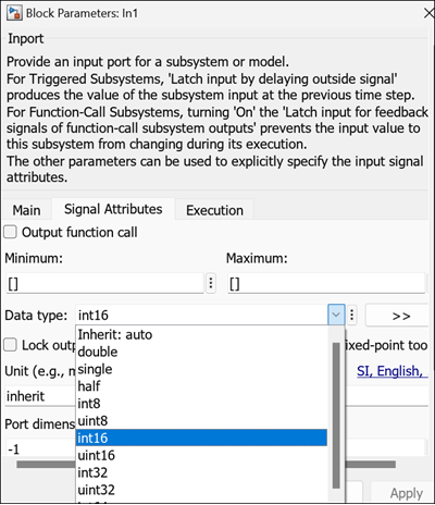
1. In the Engine_1 block, double-click the input port In1.
2. In the block dialog box, in the Signal Attributes tab, change Data type to int16 and click OK.
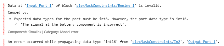
3. Simulate the model. The Diagnostic Viewer displays an error message.
4. Change Data type to int8 and click OK.
5. On the Engine_2 block, double-click the input port In1.
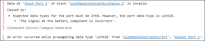
6. In the block dialog box, on the Signal Attributes tab, change Data type to uint16 and click OK.
7. Simulate the model. The Diagnostic Viewer displays an error message.
See Also
Topics
- Create Custom Constraint for Mask Parameters
- Use Port Constraints to Validate Input and Output Signals
- Validate Port Signals Among Ports of the Same Masked Block