このページの内容は最新ではありません。最新版の英語を参照するには、ここをクリックします。
システム周辺装置
R2026aさまざまなアーキテクチャで Arduino® ボードのハードウェア機能を利用して、GPIO ブロックを介したアナログ信号やデジタル信号の読み取りと書き込み、デバイス制御ブロックを介したデバイスの制御などのタスクを実行します。
ブロック
 | Analog Input | アナログ入力ピンの電圧を測定 |
 | Analog Output | Generate voltage on the specified DAC pin |
 | Analog Input SAMD | Read ADC register value after ADC conversion at the analog pin of Arduino SAMD21 core (R2023b 以降) |
 | Analog Input AVR | Read ADC register value after ADC conversion at analog pin of Arduino AVR core (R2024a 以降) |
 | Digital Input | Get logical state of digital input pin on Arduino |
 | Digital Output | Arduino 上のデジタル出力ピンの論理状態を設定 |
 | 12x8 Matrix | Graphically create a 12x8 binary matrix to define LED patterns for display (R2026a 以降) |
 | 12x8 LED Matrix | Display custom LED patterns on 12x8 LED matrix on Arduino Uno R4 Wi-Fi board (R2026a 以降) |
 | PWM Common | Generate pulse width modulated signal on analog output pin |
 | PWM SAMD | Generate pulse width modulated signal on analog output pin of Arduino SAMD21 core (R2023b 以降) |
 | PWM AVR | Generate pulse width modulated signal on analog output pin of Arduino AVR core (R2024a 以降) |
 | Input Capture | Measure frequency and duty cycle of external input signal |
 | NeoPixel | Control color and brightness of RGB and RGBW Adafruit NeoPixel LED strip (R2024a 以降) |
 | ESP32 Touch Sense | Read state of capacitive touch pins on Arduino-compatible ESP32 and ESP32-S3 boards (R2026a 以降) |
トピック
- サポートされている Arduino ハードウェア
サポートされている Arduino ハードウェアおよび Arduino 互換ボードのリスト。
- タイマーに依存しない Arduino ブロックのピン マッピング
Arduino ハードウェア ボード上でのタイマーに依存しないブロックのピン マッピング。
- Pin Mapping for Arduino Timer-Dependent Blocks
Pin mapping for blocks dependent of the timer on the Arduino hardware board.
- Model Reference Support for Arduino Driver Blocks in Simulink
Enable model hierarchy and modular design in Simulink® by using Arduino driver blocks within a referenced model.
注目の例

Generate Interrupts Using Arduino SAMD PWM Block
Use the Hardware Interrupt block to create an interrupt service routine (ISR) to react to the PWM events on your Arduino® hardware.

Get Started with Arduino SAMD Event System Using PWM and ADC Peripherals
Use the event system with Arduino Advanced PWM, Analog Input, and Hardware Interrupt blocks.
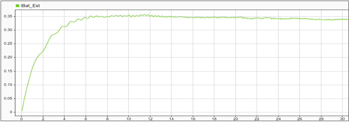
Estimate Battery Current of PMSM in Open-Loop Control Using Arduino Hardware
Use Simulink® Support Package for Arduino® Hardware to estimate the battery current of a permanent magnet synchronous machine (PMSM) in open-loop control using Motor Control Blockset™. This example also shows how to actuate a PMSM motor and calculate phase currents that are indirectly used to estimate the current of the battery.

Warn Dry Soil Moisture with Notification from IFTTT Using Arduino Based Smart Watering System
Use the WiFi HTTP Client block from the Simulink® Support Package for Arduino® Hardware to trigger a request to IFTTT once the moisture in the soil drops below a set threshold value and send a notification to an Android device.
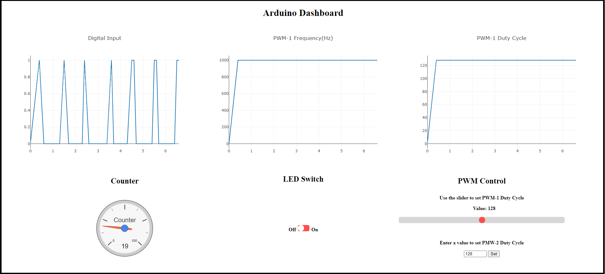
Publish Data from Arduino Blocks and Read Data on Web Browser Using WebSocket Protocols
Use the Simulink® Support Package for Arduino® Hardware to publish and subscribe data from various Arduino blocks to a WebSocket server and to read data on a web browser in a WebSocket client.
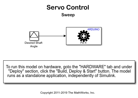
Control Standard Servo Motor Using Arduino Hardware
Use Simulink® Support Package for Arduino® Hardware to control a standard servo motor.
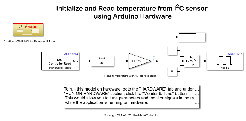
Read Temperature from I2C-Based Sensor Using Arduino Hardware
Use Simulink® Support Package for Arduino® Hardware to configure and read temperature from an I2C based sensor.
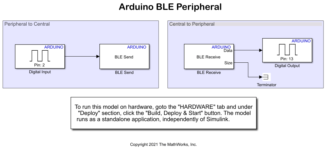
Control LED Status Using BLE Peripheral and Central Devices on Arduino Boards
Use the Simulink® Support Package for Arduino® Hardware to configure Bluetooth® Low Energy (BLE) communication between Arduino peripheral and central devices. It also shows how to control the status of an onboard LED on a peripheral device from the central device and vice versa using BLE communication.

Drive with PID Control Using Arduino Board
Simulate a simple closed-loop control algorithm in Simulink® and how to run it on an Arduino® board.
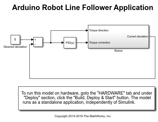
Line Follower Application for Arduino Robot
Create a line follower algorithm in Simulink® and how to run it on an Arduino® Robot.
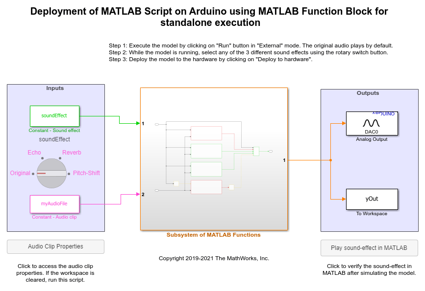
Add Echo to Audio File Stored in SD Card of Arduino Hardware
Add echo to an audio file read using the SD Card File Read block from Simulink® Support Package for Arduino® Hardware. On deployment, the Simulink model reads audio from the SD card, adds an echo effect to the audio, and then plays the audio with the echo through the headphones connected to the analog output pin of the hardware.
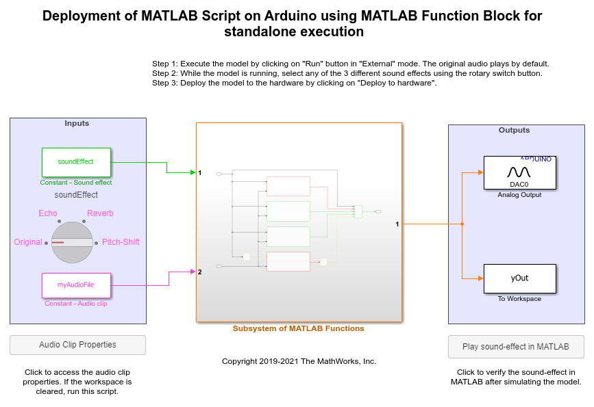
Shift Pitch of Audio File Stored in SD Card of Arduino Hardware
Shift the pitch of an audio file that is stored in an SD card of the Arduino® hardware using Simulink® Support Package for Arduino Hardware.
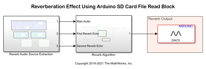
Add Reverb to Audio File Stored in SD Card of Arduino Hardware
Add reverb to an audio file read using the SD Card File Read block from Simulink® Support Package for Arduino® Hardware. On deployment, the Simulink model reads audio from the SD card, adds the reverb effect to the audio, and then plays the processed audio through the headphones connected to the analog output pin of the hardware.
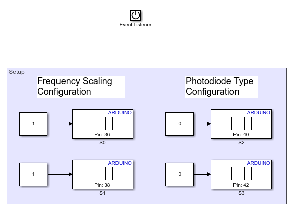
Measure Frequency and Duty Cycle Using TCS230 Color Sensor and Arduino Hardware
Use the Simulink® Support Package for Arduino® Hardware to measure frequency and duty cycle of the red color component of an object using a TCS230 color sensor and Arduino hardware.
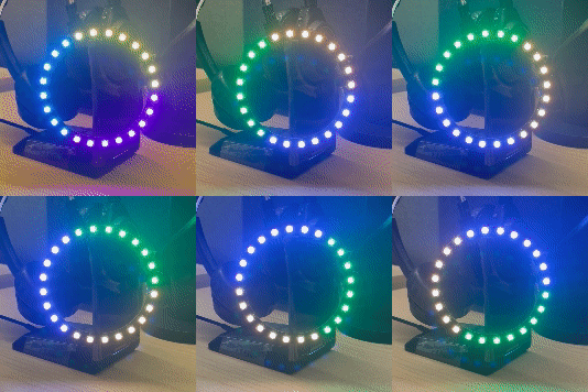
Control NeoPixel LEDs Using On-Board EEPROM on Arduino
Use the Simulink® Support Package for Arduino® Hardware to use the Adafruit® NeoPixel Digital LED strip and Arduino on-board EEPROM to create different lighting effects and patterns in External mode and Connected IO modes.
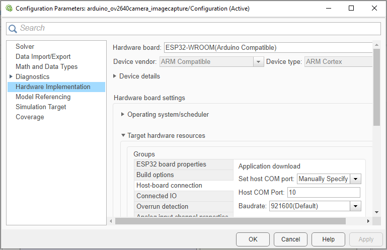
Capture Images Using ArduCam OV2640 Camera Module and ESP32 Hardware
Capture JPEG images using the ArduCam OV2640 camera module with ESP32 hardware.
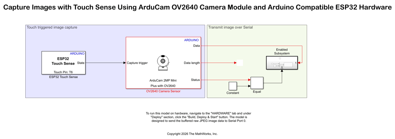
Capture Images with Touch Sense Using ArduCam OV2640 Camera Module and Arduino Compatible ESP32 Hardware
Design a touch-based image capture system using an Arduino ESP32 hardware and ArduCam OV2640 camera module. The example uses the ESP32 Touch Sense block from the Simulink® Support Package for Arduino® Hardware.

