制限モードでのモデルの取り扱い
モデルを制限モードで開くと、各種の作業を実行できます。たとえばモデルのシミュレーション、ブロック パラメーターの検査と微調整、基本的な Simulink® ブロックの追加と削除などです。実行可能な全操作の一覧は、制限モードで可能なことを参照してください。
ブロック ダイアログ ボックスを制限モードで開くと、一部のブロック パラメーターがグレー表示になっている場合があります。これらは "制限された" パラメーターで、完全モードでしか変更できません。一般に、制限モードでは数値パラメーターの値は変更できますが、ブロック パラメーター化オプションは変更できません。詳細は、ブロックのリファレンス ページを参照してください。また、制限されたパラメーターによりブロック パラメーター化スキーマが定義される場合、制限がないパラメーターのうち制限モードで微調整が可能となるものはこの制限されたパラメーターの値によって異なります。たとえば、Laminar Leakage (IL) ブロックでは [断面の形状] パラメーターが制限されています。モデルが制限モードになった時点でこのパラメーターが [円形] に設定されている場合、制限がないパラメーターのうち制限モードで微調整が可能なものは [直径] と [縦方向の長さ] です。しかし、[断面の形状] が別のオプションに設定されている場合、制限モードで使用できるパラメーターのセットは異なったものとなります。
制限モードでは物理単位は変更できません。制限モードでブロック ダイアログ ボックスを開くと、パラメーターの名前と値の横にある単位のドロップダウン リストはグレー表示されます。PS-Simulink Converter ブロックまたは Simulink-PS Converter ブロックのダイアログ ボックスを開くと、[単位] パラメーターはグレー表示されます。
以下の例では、制限モードで実行できる操作とできない操作について説明します。
制限モードでモデルのシミュレーションと微調整を行う方法
この例では、制限モードでモデルを扱い、パラメーター値を変更してシミュレーション結果を観察する方法を示します。
model_test_edit_modeモデルを開きます。このモデルは制限モードでのモデルの保存の例において制限モードで保存したものです。モデルは制限モードで開きます。
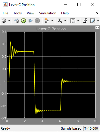
Lever C Position スコープを開いて、モデルをシミュレートします。モデルの実行とシミュレーションは制限モードで行われます。
Wheel and Axle A ブロックをダブルクリックして、ダイアログ ボックスを開きます。[機構の向き] パラメーターがグレー表示になっています。これは、制限モードではブロックの駆動方向を変更できないためです。
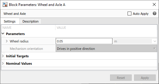
[車輪半径] パラメーターの値を
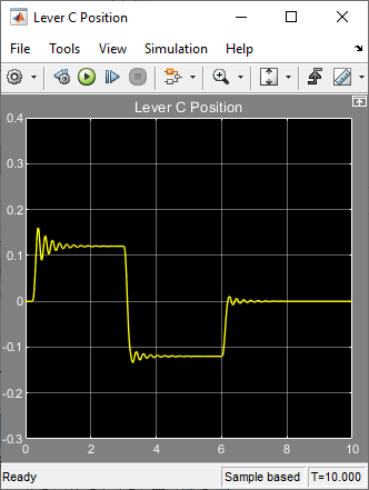
0.1に変更します。再度、モデルのシミュレーションを実行します。滑車の半径を変更した結果、ノード C の運動振幅は小さくなっています。
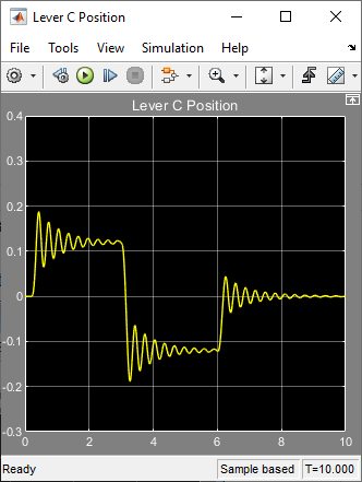
Mass ブロックをダブルクリックして、[質量] パラメーターの値を
24に変更します。モデルのシミュレーションを実行します。質量を 2 倍にした結果、振動が増加しています。
制限モードで Simulink ブロックを追加および削除する方法
この例では、基本的な Simulink ブロックを追加および削除することにより制限モードでモデルの入力信号を変更する方法を示します。
model_test_edit_modeモデルを開きます。このモデルは制限モードでのモデルの保存の例において制限モードで保存したものです。モデルは制限モードで開きます。
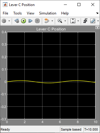
Lever C Position スコープを開いて、モデルをシミュレートします。

外部入力を正弦波に置き換えます。[コンフィギュレーション パラメーター] ダイアログ ボックスの [データのインポート/エクスポート] ペインで、[ワークスペースから読み込み] にある [入力] チェック ボックスをオフにします。Simulink の Inport ブロック、Force スコープ、および Inport ブロックをスコープに接続している信号線と Force Input サブシステムへの信号線を削除します。

Force Input サブシステムをダブルクリックして開きます。サブシステム内で、Inport ブロックを削除します。代わりに、Simulink Sources ライブラリの Sine Wave ブロックを次の図のように配置します。
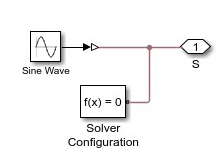
再度、モデルのシミュレーションを実行します。モデルのトポロジのすべての変更がモデルの Simulink の部分で実行されているため、モデルのコンパイルとシミュレーションが制限モードで正常に実行されます。
制限モードで許可されていない操作の実行
この例では、制限モードで許可されていない操作を実行した場合の結果を示します。
model_test_edit_modeモデルを開きます。このモデルは制限モードでのモデルの保存の例において制限モードで保存したものです。モデルは制限モードで開きます。
P サブシステムをダブルクリックして開きます。

Ideal Translational Motion Sensor ブロックの端子 [P] と PS-Simulink Converter ブロックの間の接続線を削除します。代わりに、Ideal Translational Motion Sensor ブロックの端子 [V] を PS-Simulink Converter ブロックの入力端子に接続し、レバーのノード [C] での速度を測定します。

モデルのシミュレーションを実行してみます。制限モードでトポロジが変更されたためモデルをコンパイルできないことを伝えるエラー メッセージが表示されます。変更を元に戻すか、制限モードから完全モードへの切り替えで説明されているように、完全モードに切り替えることができます。