このページの内容は最新ではありません。最新版の英語を参照するには、ここをクリックします。
Visualize Automatically Inserted Rate Transition Blocks
When you select model configuration parameter Automatically handle rate transition for data transfer for a multirate, multitasking model and you perform an update diagram, Simulink® inserts Rate Transition blocks on signal paths that cross boundaries of tasks that have different sample times. The inserted blocks are hidden by default.
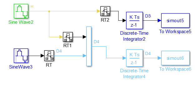
When you update the diagram, block labels appear in the model and indicate where Simulink inserted Rate Transition blocks during the compilation phase. For example, when this model is compiled, Simulink inserts Rate Transition blocks between:
Sine Wave2 block and the Mux block
SineWave3 block and the Mux block
Sine Wave2 block and Discrete-Time Integrator2 block
![]()
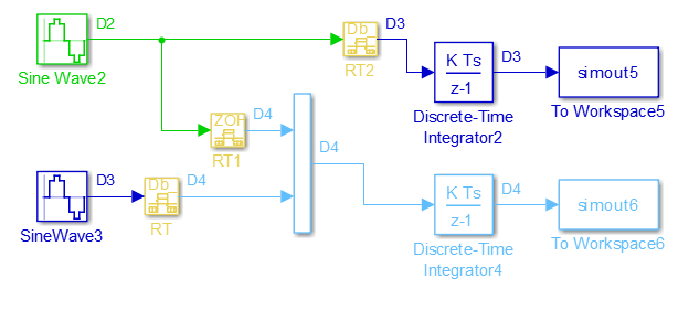
The ZOH and DbBuf block labels identify simulation behavior of the inserted blocks. For a list of block labels and their meanings, see Rate Transition.
You can show or hide the block labels. To show the block labels:
Open the Debug tab.
In the Diagnostics section, click Information Overlays.
In the Information Overlays menu, select Automatic Rate Transitions.
To configure the hidden Rate Transition blocks so that they are visible, right-click a block label and click Insert rate transition block.
When you make hidden Rate Transition blocks visible, you can:
See the simulation behavior of Rate Transition block that was inserted and the block location.
Set the block parameter Initial conditions.
Change block parameter settings to control tradeoffs, such as data integrity and latency, for the data transfer.
Validate the changes to your model by updating your diagram.
Displaying inserted Rate Transition blocks is not compatible with export-function models.
To learn more about the types of Rate Transition blocks, see Rate Transition.
参考
Automatically handle rate transition for data transfer | Rate Transition