cuboidModel
R2026bパラメトリック直方体モデルを格納するためのオブジェクト
説明
cuboidModel オブジェクトには、パラメトリック直方体モデルのパラメーターが格納されます。cuboidModel オブジェクトを作成した後、直方体の角の点や直方体の内側の点をオブジェクト関数を使用して抽出できます。直方体モデルは、pcfitcuboid 関数と pcfitcuboidalign 関数の出力を格納するために使用されます。これらの関数は点群に直方体を当てはめます。
作成
cuboidModel オブジェクトを作成する方法は 2 つあります。
cuboidModelオブジェクトで直方体のパラメーターを指定して直方体モデルを作成します。pcfitcuboid関数またはpcfitcuboidalign関数を使用して点群に直方体モデルを当てはめます。
プロパティ
この プロパティ は読み取り専用です。
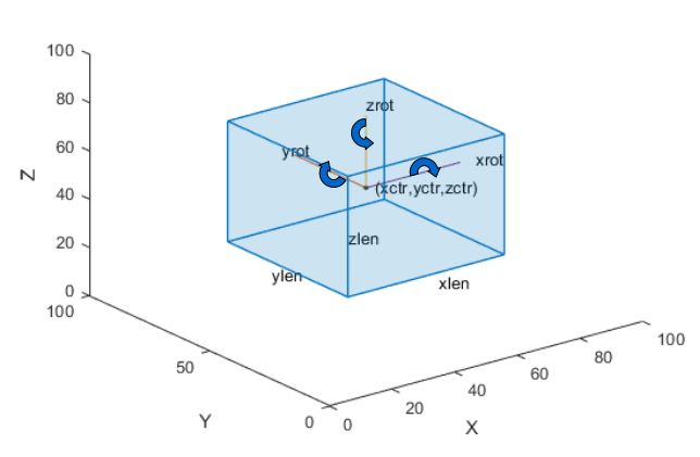
直方体モデルのパラメーター。[xctr yctr zctr xlen ylen zlen xrot yrot zrot] の形式の 9 要素行ベクトルとして格納されます。
xctr、yctr、zctr は、直方体の中心を指定します。
xlen、ylen、zlen は、回転が適用される前の直方体の x 軸、y 軸、z 軸のそれぞれの方向の長さを指定します。
xrot、yrot、zrot は、直方体の x 軸、y 軸、z 軸のそれぞれの方向の回転角度 (度) を指定します。これらの角度は、対応する軸の順方向を向いて時計回りの方向が正になります。
次の図は、これらの値によって直方体の位置がどのように決まるかを示しています。
これらのパラメーターは params 入力引数で指定されます。
データ型: single | double
この プロパティ は読み取り専用です。
直方体の中心。[xctr yctr zctr] の形式の 3 要素行ベクトルとして格納されます。このベクトルには、直方体の中心の x 軸、y 軸、z 軸のそれぞれの 3 次元座標が格納されます。
このプロパティは Parameters プロパティから派生します。
データ型: single | double
この プロパティ は読み取り専用です。
直方体の寸法。[xlen ylen zlen] の形式の 3 要素行ベクトルとして格納されます。このベクトルには、直方体の x 軸、y 軸、z 軸のそれぞれの方向の長さが格納されます。
このプロパティは Parameters プロパティから派生します。
データ型: single | double
この プロパティ は読み取り専用です。
直方体の向き (単位は度)。[xrot yrot zrot] の形式の 3 要素行ベクトルとして格納されます。このベクトルには、直方体の x 軸、y 軸、z 軸のそれぞれの方向の角度が格納されます。
このプロパティは Parameters プロパティから派生します。
向きが四元数の場合は、四元数をオイラー角 (度) に変換して直方体モデルを作成します。
データ型: single | double
オブジェクト関数
getCornerPoints | 直方体モデルの角の点を取得 |
findPointsInModel | Find points enclosed by cuboid model |
plot | 直方体モデルのプロット |
transform | Transform geometric models between coordinate frames |
例
関数 pcfitcuboid を使用して点群から直方体を検出します。この関数は直方体のパラメーターを cuboidModel オブジェクトとして格納します。
点群データをワークスペースに読み取ります。
ptCloud = pcread('highwayScene.pcd');指定した関心領域 (ROI) 内の点群を検索します。検出された点のみを含む点群を作成します。
roi = [-30 30 -20 30 -8 13];
in = findPointsInROI(ptCloud,roi);
ptCloudIn = select(ptCloud,in);
検出された点の点群をプロットします。
   figure
   pcshow(ptCloudIn.Location)
   xlabel('X(m)')
   ylabel('Y(m)')
   zlabel('Z(m)')
   title('Detected Points in ROI')
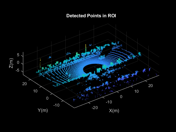
点群の指定した ROI に含まれる点のインデックスを調べます。
roi = [9.6 13.8 7.9 9.3 -2.5 3];
sampleIndices = findPointsInROI(ptCloudIn,roi);
点群の指定した点集合に直方体を当てはめます。
 model = pcfitcuboid(ptCloudIn,sampleIndices);
  figure
  pcshow(ptCloudIn.Location)
  xlabel('X(m)')
  ylabel('Y(m)')
  zlabel('Z(m)')
  title('Detect a Cuboid in a Point Cloud')
点群の直方体のボックスをプロットします。
hold on
plot(model)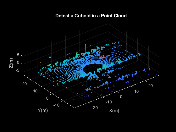
cuboidModel オブジェクトの内部プロパティを表示します。
model
model =
  cuboidModel with properties:

     Parameters: [11.4873 8.5997 -1.6138 3.6713 1.3220 1.7576 0 0 0.9999]
         Center: [11.4873 8.5997 -1.6138]
     Dimensions: [3.6713 1.3220 1.7576]
    Orientation: [0 0 0.9999]
点群データをワークスペースに読み込みます。
ptCloud = load("drivingLidarPoints.mat").ptCloud;直方体の当てはめを行う関心領域を選択します。
roi = [-10 10 -6 8 -2 2];
idx = findPointsInROI(ptCloud,roi);
ptCloudROI = select(ptCloud,idx);
トリミングされた点群を可視化します。
figure
pcshow(ptCloudROI)
title("Cropped Point Cloud")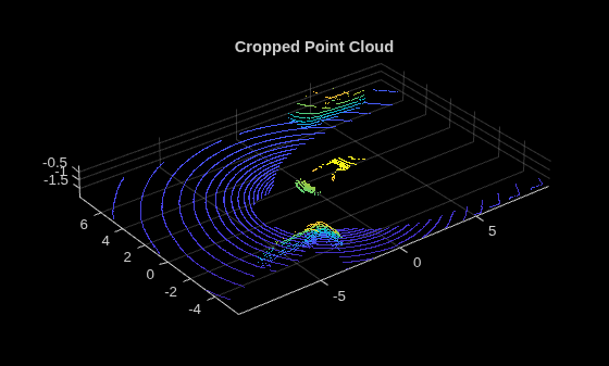
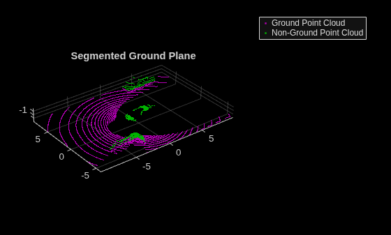
地面をセグメント化します。
maxDistance = 0.5;
[~,idxGround,idxNoGround] = pcfitplane(ptCloudROI,maxDistance);
groundPtCloud = select(ptCloudROI,idxGround);
ptCloudNoGround = select(ptCloudROI,idxNoGround);
セグメント化された地面を可視化します。
figure
pcshowpair(groundPtCloud,ptCloudNoGround)
legend("Ground Point Cloud","Non-Ground Point Cloud")
title("Segmented Ground Plane")
地面以外の点群をクラスターにセグメント化します。
minDistance = 1;
[labels,numClusters] = pcsegdist(ptCloudNoGround,minDistance);
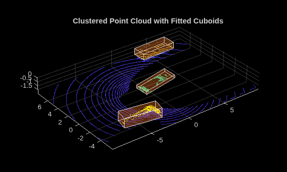
点群と各クラスターを異なる色で可視化します。
figure
pcshow(ptCloudROI)
hold on
pcshow(ptCloudNoGround.Location,labels)
直方体を各クラスターに当てはめ、各クラスターとそれに当てはめた各直方体を可視化します。
for i = 1:numClusters
    idx = find(labels == i);
    model = pcfitcuboid(ptCloudNoGround,idx);
    plot(model)
end
title("Clustered Point Cloud with Fitted Cuboids")
拡張機能
バージョン履歴
R2020b で導入参考
関数
pcfitcylinder|pcfitplane|pcfitsphere|pcfitcuboidalign|pcfitcuboid|getCornerPoints|findPointsInModel|plot|transform

