phased.IsoSpeedUnderwaterPaths
Isospeed multipath sonar channel
Description
The phased.IsoSpeedUnderwaterPaths
System object™ creates an underwater acoustic channel to propagate narrowband sound from
point to point. The channel has finite constant depth with air-water and water-bottom
interfaces. Both interfaces are planar and horizontal. Sound speed is constant
throughout the channel. The object generates multiple propagation paths in the channel
using the acoustical method of images (see [3]). Because sound speed is constant, all propagation paths are straight lines between
the source, boundaries, and receiver. There is always one direct line-of-sight path. For
each propagation path, the object outputs range-dependent time delay, gain, Doppler
factor, reflection loss, and spreading loss. You can use the channel data as input to
the multipath sound propagator, phased.MultipathChannel.
To model an isospeed channel:
Create the
phased.IsoSpeedUnderwaterPathsobject and set its properties.Call the object with arguments, as if it were a function.
To learn more about how System objects work, see What Are System Objects?
Creation
Description
channel = phased.IsoSpeedUnderwaterPathschannel.
channel = phased.IsoSpeedUnderwaterPaths(Name=Value)channel, with each specified property
Name set to the specified Value. You
can specify additional name and value arguments in any order as
(Name1=Value1,...,NameN=ValueN).
Properties
Usage
Syntax
Description
pathmat = channel(srcpos,destpos,srcvel,destvel,T)pathmat, for a
multipath underwater acoustic channel. The matrix describes one or two-way
propagation from the signal source position, srcpos, to the
signal destination position, destpos. The velocity of the
signal source is specified in srcvel and the velocity of
the signal destination is specified in destvel.
T is the step time interval.
When you use this method for one-way propagation, srcpos
refers to the origin of the signal and destpos to the
receiver. One-way propagation modeling is useful for passive sonar and
underwater communications.
When you use this method for two-way propagation, destpos
now refers to the reflecting target, not the sonar receiver. A two-way path
consists of a one-way path from source to target and then along an identical
one-way path from target to receiver (which is collocated with the source).
Two-way propagation modeling is useful for active sonar systems.
[
also returns the Doppler factor, pathmat,dop,aloss,destang,srcang]
= channel(srcpos,destpos,srcvel,destvel,T)dop, the frequency
dependent absorption loss, aloss, the receiver arrival
angles, destang, and the srcang
transmitting angles.
When you use this method for two-way propagation, destang
now refers to the reflecting target, not the sonar receiver.
Note
The object performs an initialization the first time the object is executed. This
initialization locks nontunable properties
and input specifications, such as dimensions, complexity, and data type of the input data.
If you change a nontunable property or an input specification, the System object issues an error. To change nontunable properties or inputs, you must first
call the release method to unlock the object.
Input Arguments
Output Arguments
Object Functions
To use an object function, specify the
System object as the first input argument. For
example, to release system resources of a System object named obj, use
this syntax:
release(obj)
Examples
Create a 5-path underwater sound channel and display the propagation path matrix. Assume the source is stationary and the receiver is moving along the x-axis towards the source at 20 kph. Assume one-way propagation.
speed = -20*1000/3600;
numpaths = 5;
channelpaths = phased.IsoSpeedUnderwaterPaths(ChannelDepth=200,BottomLoss=10, ...
    NumPathsSource="Property",NumPaths=numpaths,CoherenceTime=5);
tstep = 1;
srcpos = [0;0;-160];
rcvpos = [500;0;-50];
srcvel = [0;0;0];
rcvvel = [speed;0;0];
pathmat = channelpaths(srcpos,rcvpos,srcvel,rcvvel,tstep);
disp(pathmat)
    0.3356    0.3556    0.4687    0.3507    0.3791
    1.0000   -1.0000   -0.3162    0.3162   -0.3162
   54.1847   54.6850   57.0766   54.5652   55.2388
The first row contains the time delay in seconds. The second row contains the bottom reflection loss coefficients, and the third row contains the spreading loss in dB. The reflection loss coefficient for the first path is 1.0 because the direct path has no boundary reflections. The reflection loss coefficient for the second path is -1.0 because the path has only a surface reflection.
Create a 7-path underwater sound channel and display the propagation path matrix. Assume the source is stationary and the target is moving along the x-axis towards the source at 20 kph. Assume two-way propagation.
speed = -20*1000/3600;
numpaths = 7;
channelpaths = phased.IsoSpeedUnderwaterPaths(ChannelDepth=200,BottomLoss=10, ...
    NumPathsSource="Property",NumPaths=numpaths,CoherenceTime=5, ...
    TwoWayPropagation=true);
tstep = 1;
srcpos = [0;0;-160];
tgtpos = [500;0;-50];
srcvel = [0;0;0];
tgtvel = [speed;0;0];
[pathmat,dop,aloss,tgtangs,srcangs] = channelpaths(srcpos,tgtpos,srcvel,tgtvel,tstep);
disp(pathmat)
    0.6712    0.7112    0.9374    1.0354    0.7014    0.7581    1.0152
    1.0000    1.0000    0.1000    0.1000    0.1000    0.1000    0.0100
  108.3693  109.3699  114.1531  115.8772  109.1304  110.4775  115.5355
The first row contains the time delay in seconds. The second row contains the bottom reflection loss coefficients, and the third row contains the spreading loss in dB. The reflection loss coefficient for the first path is 1.0 because the direct path has no boundary reflections. The reflection loss coefficient for the second path is -1.0 because the path has only a surface reflection.
Create an underwater sound channel and plot the combined received signal. Automatically find the number of paths. Assume that the source is stationary and that the receiver is moving along the x-axis toward the source at 20 km/h. Assume the default one-way propagation.
speed = -20*1000/3600;
channel = phased.IsoSpeedUnderwaterPaths(ChannelDepth=200,BottomLoss=5, ...
    NumPathsSource="Auto",CoherenceTime=5);
tstep = 1;
srcpos = [0;0;-160];
rcvpos = [500;0;-50];
srcvel = [0;0;0];
rcvvel = [speed;0;0];
Compute the path matrix, Doppler factor, and losses. The propagator outputs 51 paths output but some paths can contain Nan values.
[pathmat,dop,absloss,rcvangs,srcangs] = channel(srcpos,rcvpos,srcvel,rcvvel,tstep);
Create of a 100 Hz signal with 500 samples. Assume that all the paths have the same signal. Use a phased.MultipathChannel System object™ to propagate the signals to the receiver. phased.MultipathChannel accepts as input all paths produced by phased.IsoSpeedUnderwaterPaths but ignores paths that have NaN values.
fs = 1e3;
nsamp = 500;
propagator = phased.MultipathChannel(OperatingFrequency=10e3,SampleRate=fs);
t = [0:(nsamp-1)]'/fs;
sig0 = sin(2*pi*100*t);
numpaths = size(pathmat,2);
sig = repmat(sig0,1,numpaths);
propsig = propagator(sig,pathmat,dop,absloss);
Plot the real part of the coherent sum of the propagated signals.
plot(t*1000,real(sum(propsig,2)))
xlabel("Time (millisec)")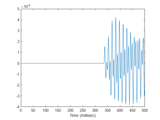
Compare the duration of a propagated signal from a stationary sonar to that of a moving sonar. The moving sonar has a radial velocity of 25 m/s away from the target. In each case, propagate the signal along a single path. Assume one-way propagation.
Define the sonar system parameters: maximum unambiguous range, required range resolution, operating frequency, and propagation speed.
maxrange = 5000.0;
rngres = 10.0;
fc = 20.0e3;
csound = 1520.0;
Use a rectangular waveform for the transmitted signal.
prf = csound/(2*maxrange);
pulseWidth = 8*rngres/csound;
pulseBW = 1/pulseWidth;
fs = 80*pulseBW;
waveform = phased.RectangularWaveform(PulseWidth=pulseWidth,PRF=prf, ...
    SampleRate=fs);
Specify the sonar positions.
sonarplatform1 = phased.Platform(InitialPosition=[0;0;-60],Velocity=[0;0;0]);
sonarplatform2 = phased.Platform(InitialPosition=[0;0;-60],Velocity=[0;-25;0]);
Specify the target position.
targetplatform = phased.Platform(InitialPosition=[0;500;-60],Velocity=[0;0;0]);
Define the underwater path and propagation channel objects.
paths = phased.IsoSpeedUnderwaterPaths(ChannelDepth=100, ...
    CoherenceTime=0,NumPathsSource="Property",NumPaths=1, ...
    PropagationSpeed=csound);
propagator = phased.MultipathChannel(SampleRate=fs,OperatingFrequency=fc);
Create the transmitted waveform.
wav = waveform();
nsamp = size(wav,1);
rxpulses = zeros(nsamp,2);
t = (0:nsamp-1)/fs;
Transmit the signal and then receive the echo at the stationary sonar.
[pathmat,dop,aloss,~,~] = paths(sonarplatform1.InitialPosition, ...
    targetplatform.InitialPosition,sonarplatform1.InitialVelocity, ...
    targetplatform.InitialVelocity,1/prf);
rxpulses(:,1) = propagator(wav,pathmat,dop,aloss);
Transmit and receive at the moving sonar.
[pathmat,dop,aloss,~,~] = paths(sonarplatform2.InitialPosition, ...
    targetplatform.InitialPosition,sonarplatform2.Velocity, ...
    targetplatform.Velocity,1/prf);
rxpulses(:,2) = propagator(wav,pathmat,dop,aloss);
Plot the received pulses.
plot(abs(rxpulses))
xlim([490 650])
ylim([0 1.65e-3])
legend("Stationary sonar","Moving sonar")
xlabel("Received Sample Time (sec)")
ylabel("Integrated Received Pulses")
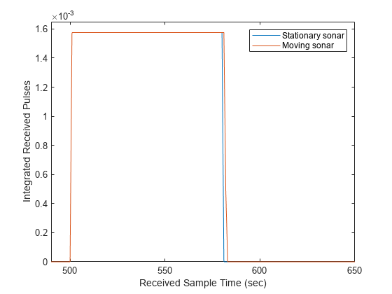
The signal received at the moving sonar has increased in duration compared to the stationary sonar.
Create an underwater sound channel and display the propagation paths which are found automatically. Assume the source is stationary and the receiver is moving along the x-axis towards the source at 20 kph. Assume two-way propagation.
speed = -20*1000/3600;
channelpaths = phased.IsoSpeedUnderwaterPaths(ChannelDepth=200,BottomLoss=5, ...
    NumPathsSource="Auto",CoherenceTime=5,TwoWayPropagation=true);
tstep = 1;
srcpos = [0;0;-160];
tgtpos = [500;0;-50];
srcvel = [0;0;0];
tgtpos = [speed;0;0];
[pathmat,dop,aloss,rcvangs,srcangs] = channelpaths(srcpos,tgtpos,srcvel,tgtpos,tstep);
Display the first 7 columns of pathmat. Some columns are filled with NaNs.
disp(pathmat(:,1:7))
    0.2107    0.2107       NaN       NaN       NaN       NaN       NaN
    1.0000    1.0000       NaN       NaN       NaN       NaN       NaN
   88.1753   88.1753       NaN       NaN       NaN       NaN       NaN
Select the column indices of the valid paths from the entire matrix.
idx = find(~isnan(pathmat(1,:)))
idx = 1×4

     1     2    27    28
Display the valid paths information.
validpaths = pathmat(:,idx)
validpaths = 3×4

    0.2107    0.2107    0.3159    0.3159
    1.0000    1.0000    0.3162    0.3162
   88.1753   88.1753   95.2131   95.2131
The first row contains the time delays in seconds. The second row contains the bottom reflected loss coefficients, and the third row contains the spreading losses.
References
[1] Urick, R.J. Principles of Underwater Sound, 3rd Edition. New York: Peninsula Publishing, 1996.
[2] Sherman, C.S. and J.Butler Transducers and Arrays for Underwater Sound. New York: Springer, 2007.
[3] Allen, J.B. and D. Berkely, “Image method for efficiently simulating small-room acoustics”, J. Acoust. Soc. Am, Vol 65, No. 4. April 1979.
Extended Capabilities
Version History
Introduced in R2017a