Generate IMU Readings on a Double Pendulum
This example shows how to generate inertial measurement unit (IMU) readings from two IMU sensors mounted on the links of a double pendulum. The double pendulum is modeled using Simscape™ Multibody™. For a step-by-step example of building a simple pendulum using Simscape Multibody, see Model a Simple Pendulum (Simscape Multibody).
open_system("doublePendulumIMU.slx");Model
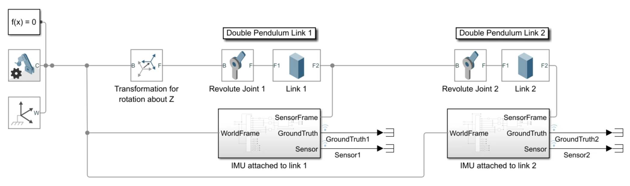
The inertial reference frame (or world frame) in Simscape Multibody defaults to the right-handed Cartesian coordinate frame. Revolute joints only apply rotations around the I-axis of the body's reference frame. At first, the inertial frame and body reference frame are aligned. The Rigid Transform block applies a rotation of -90 degrees around the X-axis of the body reference frame so that the transformed Y-axis points in the direction of the gravity vector and the link is free to rotate along the transformed Z-axis.
Use the end frames of the two links as the sensor frames of the simulated IMUs. Each IMU is defined within an IMU subsystem.
IMU Subsystem
Open the first IMU subsystem.

You can choose the reference frame of the IMU inputs to lie in the NED (North-East-Down) or ENU (East-North-Up) frame. In this simulation, you choose the ENU frame which aligns with the right-handed coordinate frame. The first Transform Sensor block measures the relative spatial relationship between the sensor frame and the inertial frame. The value for the gravitational acceleration is subtracted from the total acceleration since the IMU block incorporates gravitational acceleration in the inertial frame by default. The IMU block translates this information into accelerometer, gyroscope, and magnetometer sensor data.
The second Transform Sensor block provides the expected ground truth measurement data of the IMU. It measures the relative spatial relationship between the inertial frame and the sensor frame measured in the sensor frame, similar to the IMU. The accelerations are negated to compensate for the negation applied to acceleration in the IMU model. This is done in the IMU model to obtain zero total acceleration readings when the accelerometer is in a free fall. See imuSensor for more details on IMU modeling.
Simulate and Visualize IMU Data
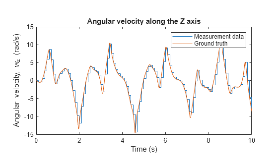
Since the primary rotations in the double pendulum are along the Z-axis of the sensor frame, the dominant accelerations measured by the IMU lie along the X and Y axes and the dominant rotations are along the *Z-*axis. The plots below show this simulated IMU data from the second IMU and compare the data with ground truth.
out = sim("doublePendulumIMU.slx");

% Simulated measurement data for the second IMU
wz = out.logsout{4}.Values.wz;
ax = out.logsout{4}.Values.ax;
ay = out.logsout{4}.Values.ay;

% Ground truth for the second IMU
wzgt = out.logsout{3}.Values.wz;
axgt = out.logsout{3}.Values.ax;
aygt = out.logsout{3}.Values.ay;

plot(wz);
hold on;
plot(wzgt);
legend("Measurement data","Ground truth");
ylabel("Angular velocity, w_z (rad/s)",Interpreter="tex")
xlabel("Time (s)")
title("Angular velocity along the Z axis")
pbaspect([2 1 1])
hold off;
plot(ax);
hold on;
plot(axgt);
legend("Measurement data","Ground truth");
ylabel("Linear acceleration, a_x (m/s^2)",Interpreter="tex")
xlabel("Time (s)")
title("Linear acceleration along the X axis")
pbaspect([2 1 1])
hold off;

plot(ay);
hold on;
plot(aygt);
legend("Measurement data","Ground truth");
ylabel("Linear acceleration, a_{y} (m/s^{2})",Interpreter="tex")
xlabel("Time (s)")
title("Linear acceleration along the Y axis")
pbaspect([2 1 1])
hold off;
