accelcal
説明
例
入力引数
出力引数
詳細
加速度計のキャリブレーション用の測定データを取得するには、加速度計の測定座標系 (X-Y-Z) の方向を次の図に示す 6 つの方向のいずれかに揃えます。たとえば、x が上向きの測定値を取得するには、1 つ目の図に示すように、加速度計の測定座標系の正の X 方向を重力の反対方向に揃えます。
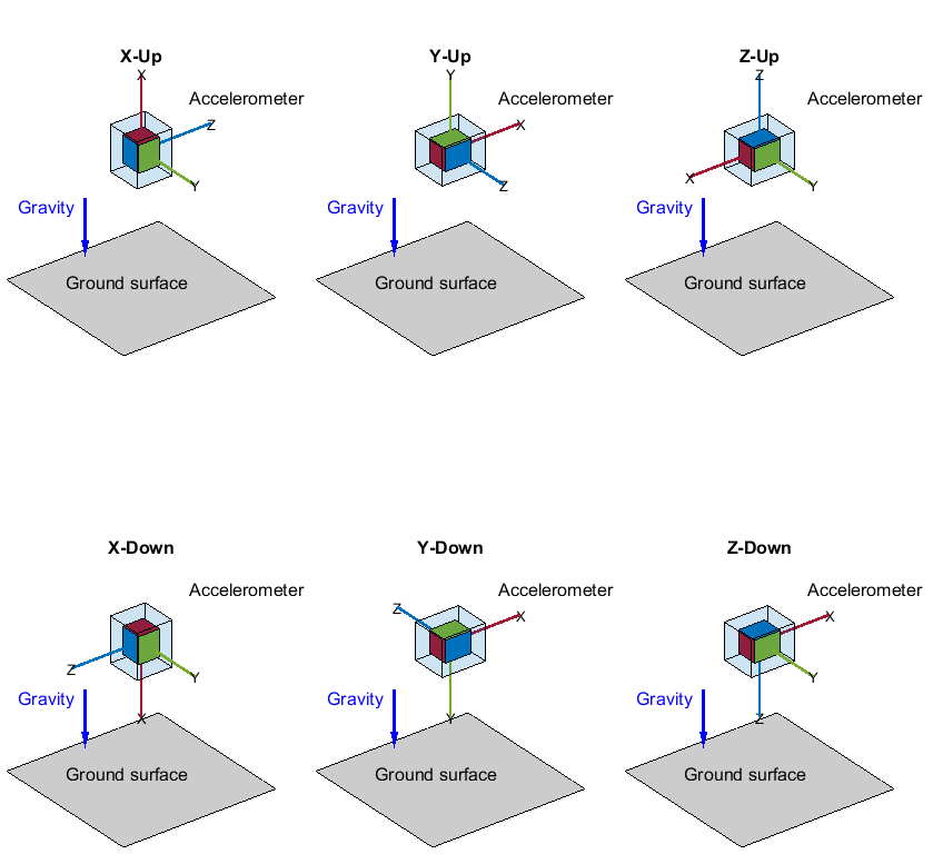
加速度計にキャリブレーション誤差が一切なく、その測定座標系が図のとおりに完全に揃っていれば、次の表に示す理想的な測定値を取得できます。
| 方向 | aX | aY | aZ |
|---|---|---|---|
| X が上向き | -g | 0 | 0 |
| X が下向き | +g | 0 | 0 |
| Y が上向き | 0 | -g | 0 |
| Y が下向き | 0 | +g | 0 |
| Z が上向き | 0 | 0 | -g |
| Z が下向き | 0 | 0 | +g |
この表の aX、aY、aZ は、それぞれ X 方向、Y 方向、Z 方向の加速度成分です。g はローカルの地球重力定数です。
参照
[1] AN4508 Application Note: Parameters and Calibration of a Low-G 3-Axis Accelerometer.
バージョン履歴
R2023b で導入