メインコンテンツ

traceDirectedRays

R2026b

Trace rays from specific origins along specific directions through optical system

Since R2026b

Description

rayBundle = traceDirectedRays(opsys) traces rays through the optical system opsys from default field points along the positive z-axis in the global coordinate system.

example

rayBundle = traceDirectedRays(opsys,Name=Value) traces rays through the optical system using additional options specified by one or more name-value arguments. For example, Directions=[0 0.1 1] specifies a ray direction with direction cosines along the global x-, y-, and z-axes.

example

Examples

collapse all

Trace a ray parallel to the optical axis from a point located before the first surface.

Load a double Gauss lens from a ZMX file into the workspace.

First, create a double Gauss optical system.

opsys = zmximport("DoubleGaussLens.zmx");

Create a field point at a global position.

fp = fieldPoint(ReferenceFrame="Global",Position=[0 3 -2]);
opsys.FieldPoints(1) = fp;

Trace rays from the field point.

rayBundle = traceDirectedRays(opsys);

Display the optical system and add the traced rays.

hv = view2d(opsys);
addRays(hv,rayBundle)
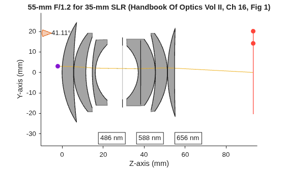
Figure contains an object of type optics.ui.opticalsystemviewer2d. The chart of type optics.ui.opticalsystemviewer2d has title 55-mm F/1.2 for 35-mm SLR (Handbook Of Optics Vol II, Ch 16, Fig 1).

Load a double Gauss lens from a ZMX file into the workspace.

Create a double Gauss optical system.

opsys = zmximport("DoubleGaussLens.zmx");

Define multiple origin points and ray directions.

origins = [0 0 -3; 0 0 -4; 0 1 -3; 0 -1 -2];
dirs = [0 0 1; 0 cosd(75) cosd(15); 0 cosd(80) cosd(10); 0 cosd(65) cosd(25)];

Trace rays at a single wavelength with all ray properties.

lambda = 550;
rayBundle = traceDirectedRays(opsys,Origins=origins,Directions=dirs,Wavelengths=lambda,RayProperties="All");

Display the optical system in 2-D and add the traced rays.

hv = view2d(opsys);
addRays(hv,rayBundle)
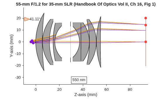
Figure contains an object of type optics.ui.opticalsystemviewer2d. The chart of type optics.ui.opticalsystemviewer2d has title 55-mm F/1.2 for 35-mm SLR (Handbook Of Optics Vol II, Ch 16, Fig 1).

Input Arguments

collapse all

Optical system, specified as an opticalSystem object.

Name-Value Arguments

collapse all

Specify optional pairs of arguments as Name1=Value1,...,NameN=ValueN, where Name is the argument name and Value is the corresponding value. Name-value arguments must appear after other arguments, but the order of the pairs does not matter.

Example: rayBundle = traceDirectedRays(opsys,Directions=[0 0.1 1]) specifies a ray direction with direction cosines along the global x-, y-, and z-axes.

Starting points for ray tracing, specified as one of these values:

  • N-by-3 numeric matrix — Each row contains the [x y z] global coordinates for one origin point. N is the number of rays.

  • Array of FieldPosition objects — Each field point must have a "Global" or "Object" reference frame.

By default, the starting field points are the FieldPosition objects in the FieldPoints property of the opticalSystem object, defined relative to a global or object coordinate system. If the optical system does not contain any field points, then the function uses a field point at the global position [0 0 −0.2(Zext)], where Zext is the total axial extent of the optical system geometry along the global z‑axis.

Ray direction cosines, specified as one of these options:

  • 1-by-3 numeric vector — The direction cosines of a single ray along the x-, y-, and z-axes in global coordinates. The function traces this direction from every origin.

  • N-by-3 numeric matrix — The direction cosines of N rays. Each row contains the direction cosines of a ray along the x-, y-, and z-axes in global coordinates. The function traces all N directions from every origin. N is the number of rays.

The function normalizes the directions automatically, so you do not need to normalize each row.

Data Types: double

Wavelengths for ray tracing, specified as an M-element numeric vector, in nanometers. The function traces every ray at each wavelength. M is the number of wavelengths.

Data Types: double

Additional ray properties to compute, specified as a string scalar, string array, character vector, or cell array of character vectors with one or more of these values.

The traceDirectedRays function returns the specified ray properties as additional fields in the RayData property of rayBundle. Each value of RayProperties, except "All", creates a field of the same name in RayData.

RayProperties ValueField Value in RayData

"FresnelTerms"

Fresnel reflection and transmission coefficients at each interface, bulk transmission and phase shift, and the total transmittance through the optical system, represented as a structure with these fields.

  • SystemTransmittance — Total transmission through the entire optical system, represented as an N-by-1 vector. Each element of the vector is the total transmission for the corresponding ray. N is the number of traced rays.

  • rs — Reflection amplitude coefficient, or complex ratio, for s-polarized incident light, represented as an N-by-MaxRayLength complex-valued matrix. MaxRayLength is the maximum number of surfaces intersected by any ray.

  • rp — Reflection amplitude coefficient, or complex ratio, for p-polarized incident light, represented as an N-by-MaxRayLength complex-valued matrix.

  • ts — Transmission amplitude coefficient, or complex ratio, for s-polarized incident light, represented as an N-by-MaxRayLength complex-valued matrix.

  • tp — Transmission amplitude coefficient, or complex ratio, for p-polarized incident light, represented as an N-by-MaxRayLength complex-valued matrix.

  • Rs — Reflection power coefficient, which signifies the reflectance, for s-polarized incident light, represented as an N-by-MaxRayLength matrix.

  • Rp — Reflection power coefficient, which signifies the reflectance, for p-polarized incident light, represented as an N-by-MaxRayLength matrix.

  • Ts — Transmission power coefficient, which signifies the transmittance, for s-polarized incident light, represented as an N-by-MaxRayLength matrix.

  • Tp — Transmission power coefficient, which signifies the transmittance, for p-polarized incident light, represented as an N-by-MaxRayLength matrix.

  • BulkTransmission — Transmission coefficient for each ray as it propagates through the bulk medium before reaching the intersected surface, represented as an N-by-MaxRayLength matrix. Each element (i, j) represents the bulk transmission of ray i as it propagates to surface j. This value accounts for any absorption or attenuation that occurs along the ray's path before it interacts with a boundary or interface. For example, a value of 1 indicates perfect transmission, or zero loss. Values between 0 and 1 represent partial transmission due to absorption or scattering in the bulk material.

  • BulkPhaseshift — Accumulated phase shift experienced by each ray as it traverses the bulk medium before reaching the intersected surface, represented as an N-by-MaxRayLength matrix. Each element (i, j) represents the bulk phase shift angle, in degrees, of ray i as it propagates to surface j. This value accounts for any absorption or attenuation that occurs along the ray's path before it interacts with a boundary or interface. For example, a value of 0 means no phase shift occurs, or the ray has not traveled any distance. Positive values indicate accumulated phase shift due to propagation.

"PolarizationMatrices"

Polarization transformation matrices for each ray and surface intersection, represented as a structure with these fields.

  • BulkMatrix — Polarization change matrix for propagation within each segment as the ray travels through a bulk medium between two surfaces, represented as an N-by-MaxRayLength-by-3-by-3 complex array. For any given index in the first dimension i and second dimension j, BulkMatrix(i,j,:,:) is a 3-by-3 complex matrix that represents the polarization transformation experienced by ray i as it propagates through the medium between surfaces j and j – 1. This matrix describes the effect of the bulk material on the polarization state along each segment of the ray path.

  • SurfaceMatrix — Polarization change matrix at each ray-surface intersection, represented as an N-by-MaxRayLength-by-3-by-3 complex array. For any given index in the first dimension i and second dimension j, SurfaceMatrix(i,j,:,:) is a 3-by-3 complex matrix that represents the polarization transformation experienced by ray i at surface j. This matrix describes how the polarization state changes due to the reflection, refraction, or transmission at each surface that a ray encounters along its path.

  • SystemMatrix — Overall polarization change matrix for each ray, represented as an N-by-3-by-3 complex array. Each slice SystemMatrix(i,:,:) is a 3-by-3 complex matrix that represents the cumulative polarization change for the ray i.

"All"

Adds all additional ray properties to RayData.

Data Types: string | char | cell

Output Arguments

collapse all

Traced ray data, returned as an array of RayBundle objects.

Version History

Introduced in R2026b