Specific Dissipation Heat Exchanger (TL)
Heat exchanger parameterized by specific dissipation data for systems with thermal liquid and controlled flows
Since R2024a
Libraries:
Simscape /
Fluids /
Heat Exchangers /
Thermal Liquid
Description
The Specific Dissipation Heat Exchanger (TL) block models the cooling and heating of fluids through conduction over a thin wall. The properties of a single-phase thermal liquid are defined on the Thermal Liquid tab. The second fluid is a controlled fluid, which is specified only by the user-defined parameters on the Controlled Fluid tab. It does not receive any properties from the domain fluid network. The heat exchange between the fluids is based on the thermal liquid sensible heat.
Heat Transfer Model
Heat transfer by the simple model is based on specific dissipation:
where:
ξ is specific dissipation, which is a function of the mass flow rates of the thermal and controlled liquids.
TIn,Th is the thermal liquid inlet temperature.
TIn,C is the controlled liquid inlet temperature.
The simple model is based on linear interpolation of user-provided tabulated data and does not capture individual features of the heat exchanger.
The fluid properties that the block uses in heat transfer calculations are the average between the value at the inlet and the value in the fluid volume.
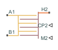
Composite Structure
The Heat Exchanger (TL) block is a composite of the Specific Dissipation Heat Exchanger Interface (TL) and Specific Dissipation Heat Transfer blocks:

Examples

Engine Cooling System
Model an engine cooling system with an oil cooling circuit.

House Heating System
Model a simple house heating system. The model contains a heater, a controller, and a house structure with four radiators and four rooms. Each room exchanges heat with the environment through its exterior walls, roof, and windows. Each path is simulated as a combination of a thermal convection, thermal conduction, and the thermal mass. It is assumed that heat is not transferred internally between rooms. The heater consists of a furnace, a boiler, an accumulator, and a pump to circulate hot water in the system. The controller starts admitting fuel into the furnace if the overall average temperature of rooms falls below 21 degree C and it stops if the temperature exceeds 25 degree C. The simulation calculates the heating cost and indoor temperatures.

Hydraulic Oil System with Thermal Control
A hydraulic oil system with a thermal control using Simscape™ Fluids™ Thermal Liquid blocks. The hydraulic oil system consists of an oil storage tank represented by the Tank (TL) block with two inlets, a pump represented by a Mass Flow Rate Source (TL) block, and pipelines represented by Pipe (TL) block.