このページは機械翻訳を使用して翻訳されました。最新版の英語を参照するには、ここをクリックします。
Simulink 信号と HDL 信号を視覚的に比較する
チュートリアル:概要
メモ
このチュートリアルと使用するツールは ModelSim® ユーザー向けですが、同様のツールを使用する Xcelium™ ユーザーでもプロセスの大部分は同じです。詳細については、HDL シミュレータのドキュメントを参照してください。
VCD ファイルには、後処理ツールを使用してグラフィカルに表示したり分析したりできるデータが含まれています。このようなツールの例としては、VCD ファイルを WLF ファイルに変換し、それを ModelSim wave ウィンドウで表示できる ModelSim vcd2wlf ツールがあります。このチュートリアルでは、vcd2wlf ツールを適用する方法を説明します。
チュートリアル:手順
このチュートリアルでは、マンチェスター受信機(絶対時間モード) の例のモデルを使用します。VCD データを表示するには、次の手順を実行します。
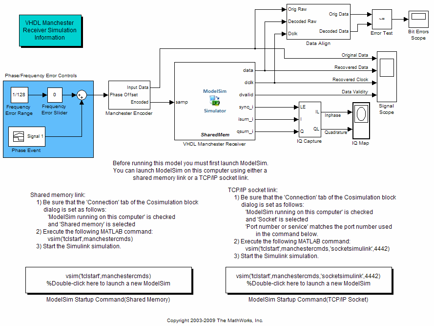
Manchester Receiver Simulink® サンプル モデル
abs_manchestermodel.slxのコピーを書き込み可能なフォルダーに配置します。Manchester Receiver モデルの書き込み可能なコピーを開きます。Simulation タブの File セクションで、Open をクリックします。ファイル
abs_manchestermodelを選択し、Openをクリックします。Simulink モデルは次のように表示されます。HDL コシミュレーション ブロックには、「VHDL Manchester Receiver」というマークが付いています。
マンチェスター レシーバー モデルの番号付き手順に従わないでください。このチュートリアルで提供されている手順のみに従ってください。
ライブラリ ブラウザーを開きます。
次のように、Signal Scope ブロックを To VCD File ブロックに置き換えます。
Signal Scope ブロックを削除します。そのブロックへの信号接続を表す線が破線に変わり、切断されたことを示します。
HDL Verifier™ ブロック ライブラリを見つけて開きます。
「Mentor Graphics® ModelSim で使用する」をクリックすると、ModelSim で使用するための HDL Verifier Simulink ブロックにアクセスできます。
To VCD File ブロックをクリックして、ブラウザからモデル ウィンドウ内の Signal Scope ブロックが以前占めていた場所にドラッグし、ライブラリ ブラウザからモデルに To VCD File ブロックをコピーします。
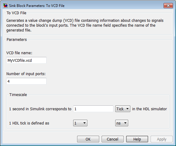
To VCD File ブロックアイコンをダブルクリックします。[ブロック パラメーター] ダイアログ ボックスが表示されます。
VCD file name テキスト ボックスに
MyVCDfile.vcdと入力します。Number of input ports テキスト ボックスに
4と入力します。
OK をクリックします。Simulink は新しいパラメータをブロックに適用します。
信号
Original Data、Recovered Data、Recovered Clock、Data Validityをブロック ポートに接続します。次の表示では、モデルの変更された領域が強調表示されます。
モデルを保存します。
デモ モデルに表示される説明テキストから次のコマンド ラインを選択します。
vsim('tclstart',manchestercmds,'socketsimulink',4442)コマンドを MATLAB® コマンド ウィンドウに貼り付けて、コマンド ラインを実行します。このコマンドは、ModelSim を起動し、Simulink 協調シミュレーション セッション用に構成します。
HDL コシミュレーション ブロック パラメータ ダイアログ ボックスを開き、Connection タブを選択します。接続方法をソケットに変更し、TCP/IP ソケット ポートを「4442」に変更します。ここで指定するポートは、前の手順の
vsimコマンドの呼び出しで指定された値と一致する必要があります。Simulink モデル ウィンドウからシミュレーションを開始します。
シミュレーションが完了したら、生成された VCD ファイル
MyVCDfile.vcd(任意のテキスト エディターでかまいません) を見つけて開き、参照します。VCD ファイルを閉じます。
入力フォーカスを ModelSim に変更し、シミュレーションを終了します。
現在のフォルダを VCD ファイルを含むフォルダに変更し、ModelSim コマンド プロンプトで次のコマンドを入力します。
vcd2wlf MyVCDfile.vcd MyVCDfile.wlf
vcd2wlfユーティリティは、VCD ファイルを、コマンドvsim -viewで表示する WLF ファイルに変換します。ModelSim で、次のコマンドを入力して、wave ファイル
MyVCDfile.wlfをデータ セットMyVCDwlfとして開きます。vsim -view MyVCDfile.wlf
次のコマンドで
MyVCDwlfデータ セットを開きます。add wave MyVCDfile:/*
VCD ファイルに記録された信号を表示する wave ウィンドウが表示されます。
信号データを表示するには、[ズーム フル] ボタン
 をクリックします。wave ウィンドウは次のように表示されます。
シミュレーションを終了します。終了する方法の 1 つは、次のコマンドを入力することです。
dataset close MyVCDfile
ModelSim はデータ セットを閉じ、wave ウィンドウをクリアして、シミュレーションを終了します。
vcd2wlf ユーティリティとデータ セットの操作の詳細については、ModelSim のドキュメントを参照してください。