Generate Custom Comments from Block Annotations
This example shows how to render annotations connected to blocks as comments in the generated code.
Compared to block descriptions, annotations offer the following advantages:
Annotations appear on the Simulink® canvas, where you can create, view, and edit them directly.
You can connect annotations across multiple blocks. You can also connect multiple annotations to one block.
You can insert equations and tables in annotations and display them as code comments.
Inspect Annotations in Simulink Model
Open the example model.
model = 'CustomCodeComments';
open_system(model)
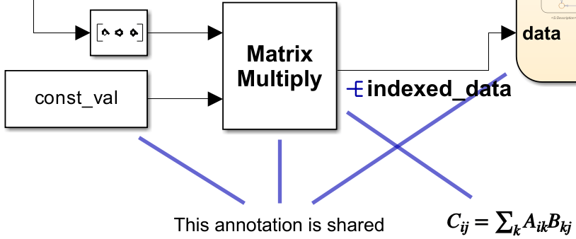
This model contains two annotations connected to blocks:
A plain text annotation connected to the Constant, Matrix Multiply, and Stateflow® blocks (see Create Text Annotations).
An equation annotation connected to the Matrix Multiply block (see Add Equations to Text Annotations).
To connect annotations to blocks, see Associate Annotations with Blocks and Areas.

Insert Annotations as Comments
1. Open the Configuration Parameters dialog box. In the Code Generation pane, set the System Target File parameter to ert.tlc.
set_param(model,SystemTargetFile='ert.tlc');2. In the Comments pane, select the Connected annotations in block comments parameter.
set_param(model,AnnotationsInComments='on');3. Build the model and generate code.
slbuild(model);
### Searching for referenced models in model 'CustomCodeComments'.
### Total of 1 models to build.
### Starting build procedure for: CustomCodeComments
### Successful completion of build procedure for: CustomCodeComments

Build Summary

Top model targets:

Model               Build Reason                                         Status                        Build Duration
=====================================================================================================================
CustomCodeComments  Information cache folder or artifacts were missing.  Code generated and compiled.  0h 0m 19.138s

1 of 1 models built (0 models already up to date)
Build duration: 0h 0m 19.953s
The code generator renders your annotations as comments in the code.
cfile = fullfile('CustomCodeComments_ert_rtw','CustomCodeComments.c');
coder.example.extractLines(cfile,"Product: '<Root>/Product' incorporates:", 'Gateway: Stateflow', 1, 0);
  /* Product: '<Root>/Product' incorporates:
   *  Constant: '<Root>/Constant'
   *  Inport: '<Root>/In1'
   *  Inport: '<Root>/In2'
   *  Inport: '<Root>/In3'
   *  Inport: '<Root>/In4'
   *
   * Block description for '<Root>/Product':
   *  This block determines the output index by taking the inner product of
   *  the vector of inputs and [1 2 3 4].
   *
   * Annotations for '<Root>/Product':
   *  $C_{ij} = \sum_k A_{ik} B_{kj}$
   *  This annotation is shared
   *
   *
   * Annotations for '<Root>/Constant':
   *  This annotation is shared
   */
  indexed_data = ((rtU.In1 * const_val[0] + rtU.In2 * const_val[1]) + rtU.In3 *
                  const_val[2]) + rtU.In4 * const_val[3];

  /* Chart: '<Root>/Stateflow'
   *
   * Block description for '<Root>/Stateflow':
   *  Stateflow block decides the index output by following logic
   *  1. If one and only one input signal is enabled, the index will
   *  refer to the enabled signal line.
   *  2. Otherwise, maintain the old value.
   *
   * Annotations for '<Root>/Stateflow':
   *  This annotation is shared
   */
When a block has multiple annotations, the code generator places each annotation on a separate line. When equations are present, the code generator renders the underlying MathML or LaTeX code. Finally, note that annotation comments appear alongside block description comments.
Limitations
The following annotations do not appear as comments in the generated code:
Annotations not connected to model elements, including area annotations
Annotations attached to a block that is reduced
The following elements of annotations do not appear in comments:
Images
Text formatting, including bold, underline, or italicize
You cannot trace directly between an annotation and its associated code comments. However, you can trace between a block with connected annotations and its code comments. See Trace Simulink Model Elements in Generated Code for more information on model-code traceability.