Resolver Peripheral Configuration
Description
Add-On Required: This feature requires the Embedded Coder Support Package for Infineon AURIX TC4x Microcontrollers add-on.
View and edit the map of peripherals in the Infineon® AURIX™ model to the hardware peripherals.
Using the Hardware Mapping tool, you can:
View and edit configuration parameters of the Resolver peripheral block.
Check for any conflicts between the peripherals.
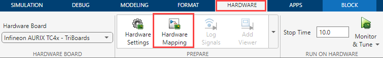
Open the Resolver Peripheral Configuration
In the Hardware tab, click Hardware Mapping.
Parameters
Global parameters
Enable to configure excitation carrier waveform parameters.
Specify the type of excitation carrier waveform.
Dependencies
To enable this parameter, select the Carrier wave parameter.
Specify the frequency of excitation carrier waveform.
Dependencies
To enable this parameter, select the Carrier wave parameter.
Select positive PWM pin for carrier excitation.
Dependencies
To enable this parameter, select the Carrier wave parameter.
Select negative PWM pin for carrier excitation.
Dependencies
To enable this parameter, select the Carrier wave parameter.
Select output mode of the PWM pin for carrier excitation.
Dependencies
To enable this parameter, select the Carrier wave parameter.
Select speed of the PWM pin for carrier excitation.
Dependencies
To enable this parameter, select the Carrier wave parameter.
Select voltage level of the PWM pin for carrier excitation.
Dependencies
To enable this parameter, select the Carrier wave parameter.
Select to enable bit reverse mode for excitation carrier waveform.
Dependencies
To enable this parameter, select the Carrier wave parameter.
Select to enable inverted polarity for excitation carrier waveform.
Dependencies
To enable this parameter, select the Carrier wave parameter.
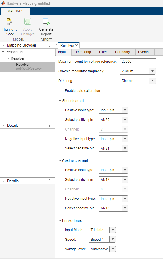
Input
Maximum count for full-scale voltage.
Select the on-chip modulator frequency.
Note
The available options vary based on the value of External oscillator (MHz). Click Model Settings and navigate to Configuration Parameters > Hardware Implementation > Target hardware resources > Clocking > External oscillator (MHz) in the Simulink® model to change its value.
Add dithering (white noise), if required.
Enable auto calibration of the delta-sigma conversion.
Specify the type of calibration for the delta-sigma conversion.
Dependencies
To enable this parameter, select the Enable auto calibration parameter.
Input > Sine channel
Type of positive input of the sine channel for delta-sigma conversion.
Note
The resolver module supports differential inputs where you can configure positive and negative inputs accordingly. In case of a single-ended application, you can configure the unused pin to the ground.
Select pin number of the sine channel positive pin.
Dependencies
To enable this parameter, set the Positive input type
parameter to Input-pin.
Type of negative input of the sine channel for delta-sigma conversion.
Select pin number of the sine channel negative pin.
Dependencies
To enable this parameter, set the Negative input type
parameter to Input-pin.
Input > Cosine channel
Type of positive input of the cosine channel for delta-sigma conversion.
Note
The resolver module supports differential inputs where you can configure positive and negative inputs accordingly. In case of a single-ended application, you can configure the unused pin to the ground.
Select pin number of the cosine channel positive pin.
Dependencies
To enable this parameter, set the Positive input type
parameter to Input-pin.
Type of negative input of the cosine channel for delta-sigma conversion.
Select pin number of the cosine channel negative pin.
Dependencies
To enable this parameter, set the Negative input type
parameter to Input-pin.
Input > Pin settings
Select the input mode for the resolver pin(s).
Select the pin speed for the resolver pin.
Select the voltage level for the resolver pin.
Filter > CIC Filter
Decimation factor for delta-sigma conversion. Higher the value of Decimation factor, higher will be the accuracy, at the cost of additional time.
Filter > Offset compensation
Enable offset compensation for delta-sigma conversion.
Cutoff frequency for offset compensation.
Dependencies
To enable this parameter, select the Enable offset compensation parameter.
Specify the offset voltage in volts.
Dependencies
To enable this parameter, select the Enable offset compensation parameter.
Filter > Rectifier
Select the sign signal source for the excitation carrier.
Specify the carrier frequency for the rectifier channel.
Dependencies
To enable this parameter, set the Sign-signal source
parameter to Channel result or External
pin.
Select external source pin for the sign-signal.
Dependencies
To enable this parameter, set the Sign-signal source
parameter to External pin.
Enable to automatically assign sign delays.
Specify the delay of sine channel.
Dependencies
To enable this parameter, select the Auto assign
sign-delays parameter.
Specify the delay of cosine channel.
To enable this parameter, select the Auto assign
sign-delays parameter.
Filter > Integrator
Specify the number of values to discard during integration.
Specify the number of carrier cycles to integrate.
This is a read only parameter, which indicates the number of samples selected based on the Number of carrier cycles to integrate parameter.
Timestamp
Specify the frequency of timestamp.
Dependencies
To enable this parameter, set the Enable timestamp parameter in the Resolver block in the Simulink model.
Specify the hardware trigger source for timestamp.
Note
Ensure that you have configured the appropriate trigger from the PWM block with a rate (1/initial clock frequency of PWM) that must be greater than or equal to 4 times the Output rate in seconds parameter tab in Resolver Peripheral Configuration tool. This is due to the availability of two results, one for each sine and cosine channels.
Dependencies
To enable this parameter, select the Enable timestamp parameter in the Resolver block in the Simulink model.
Specify the type of hardware trigger for timestamp.
Dependencies
To enable this parameter, select theEnable timestamp parameter in the Resolver block in the Simulink model.
Specify hardware trigger edge for timestamp.
Dependencies
To enable this parameter, select the Enable timestamp parameter in the Resolver block in the Simulink model.
Specify the trigger delay for timestamp.
Dependencies
To enable this parameter, select theEnable timestamp parameter in the Resolver block in the Simulink model.
This a read only parameter indicating the minimum rate at which the resolver module updates the output. Its value depends on On-chip modulator frequency (MHz), Decimation factor (3-1023), and Number of values for accumulation parameters.
Dependencies
To enable this parameter, select theEnable timestamp parameter in the resolver block in the Simulink model.
Boundary > Sine channel
Specify the lower limit for the boundary band for checking the result.
Specify the upper limit for the boundary band for checking the result.
Enable hysteresis to avoid metastable states and switching due to internal ground bounce.
Specify boundary mode for the sine channel.
Dependencies
To enable this parameter, select the Enable hysteresis on boundary flag parameter.
Specify the service request based on the boundary mode.
Boundary > Boundary flag connection
Specify the number of boundary flag connections for the sine channel.
Dependencies
To enable this parameter, set the Boundary flag
parameter to Inside boundary band,
Outside boundary band, or Out of
bound.
Boundary > Sine channel boundary flag connection #
Specify the module for boundary flag connections.
Dependencies
To enable this parameter, set the Number of connections parameter to a value greater than 0.
Specify the channels for boundary flag connections.
Dependencies
To enable this parameter, set the Number of connections parameter to a value greater than 0.
Boundary > Cosine channel
Specify the lower limit for the boundary band for checking the result.
Specify the upper limit for the boundary band for checking the result.
Enable hysteresis to avoid metastable states and switching due to internal ground bounce.
Specify the boundary mode for cosine channel.
Dependencies
To enable this parameter, set the Enable hysteresis on boundary flag parameter.
Specify service request based on the boundary mode.
Boundary > Boundary flag connection
Specify the number of boundary flag connections for the cosine channel.
Dependencies
To enable this parameter, set the Boundary flag
parameter to Inside boundary band,
Outside boundary band, or Out of
bound.
Boundary > Cosine channel boundary flag connection #
Specify the module for boundary flag connections.
Dependencies
To enable this parameter, set the Number of connections parameter to a value greater than 0.
Specify the channels for boundary flag connections.
Dependencies
To enable this parameter, set the Number of connections parameter value as greater than 0.
Events > Main filter result
Enable interrupt for main filter.
Specify interrupt channel for the main filter
Dependencies
To enable this parameter, set the Enable interrupt parameter.
Specify interrupt condition for the main filter. To limit the conversion interrupts, select the gate-signal option.
Dependencies
To enable this parameter, set the Enable interrupt parameter.
Specify the source of the gate signal to trigger the main filter result.
Note
Ensure that you have configured the appropriate trigger using the PWM block.
Dependencies
To enable this parameter, set the Interrupt parameter
to Only while gate is high or Only
while gate is low.
Hardware trigger for the main filter result.
Dependencies
To enable this parameter, set the Interrupt parameter
to Only while gate is high or Only
while gate is low.
Trigger delay for the main filter result.
Dependencies
To enable this parameter, set the Interrupt parameter
to Only while gate is high or Only
while gate is low.
Events > Timestamp
Enable interrupt for timestamp.
Specify interrupt channel for the timestamp.
Dependencies
To enable this parameter, set the Enable interrupt parameter.
Version History
Introduced in R2024a
See Also
MATLAB Command
You clicked a link that corresponds to this MATLAB command:
Run the command by entering it in the MATLAB Command Window. Web browsers do not support MATLAB commands.
Web サイトの選択
Web サイトを選択すると、翻訳されたコンテンツにアクセスし、地域のイベントやサービスを確認できます。現在の位置情報に基づき、次のサイトの選択を推奨します:
また、以下のリストから Web サイトを選択することもできます。
最適なサイトパフォーマンスの取得方法
中国のサイト (中国語または英語) を選択することで、最適なサイトパフォーマンスが得られます。その他の国の MathWorks のサイトは、お客様の地域からのアクセスが最適化されていません。
南北アメリカ
- América Latina (Español)
- Canada (English)
- United States (English)
ヨーロッパ
- Belgium (English)
- Denmark (English)
- Deutschland (Deutsch)
- España (Español)
- Finland (English)
- France (Français)
- Ireland (English)
- Italia (Italiano)
- Luxembourg (English)
- Netherlands (English)
- Norway (English)
- Österreich (Deutsch)
- Portugal (English)
- Sweden (English)
- Switzerland
- United Kingdom (English)