指定した帯域幅の MIMO 制御システムの調整
この例では、looptune を使って次の制御システムを調整し、0.1 ~ 1 rad/s のループ交差周波数を実現する方法を説明します。

プラント G は 2 入力 2 出力のモデルです (y は 2 要素ベクトル信号)。この例では、G の伝達関数は次のようになります。
このサンプル プラントは、蒸留塔の分離コントローラーの例で詳しく説明した蒸留塔に基づいています。
この制御システムを調整するには、最初にプラントの数値モデルを作成します。次に、コントローラー要素の調整可能なモデルを作成し、それらを相互接続してコントローラー モデルを構築します。その後、looptune を使用してコントローラー モデルの自由パラメーターを調整します。最後に、調整後のシステムのパフォーマンスを調べて、調整したコントローラーが目的の性能を実現しているか確認します。
プラントのモデルを作成します。
s = tf('s');
G = 1/(75*s+1)*[87.8 -86.4; 108.2 -109.6];
G.InputName = {'qL','qV'};
G.OutputName = 'y';
制御システムを調整する場合、looptune はチャネル名 G.InputName および G.OutputName を使用してプラントとコントローラーを相互接続します。したがって、図に合わせてこれらのチャネル名を割り当てます。G.OutputName = 'y' を設定した場合、G.OutputName は自動的に {'y(1)';'y(2)'} に展開されます。この展開は、G が 2 出力システムであるために生じます。
コントローラーのコンポーネントを表します。
D = tunableGain('Decoupler',eye(2));
D.InputName = 'e';
D.OutputName = {'pL','pV'};

PI_L = tunablePID('PI_L','pi');
PI_L.InputName = 'pL';
PI_L.OutputName = 'qL';

PI_V = tunablePID('PI_V','pi');
PI_V.InputName = 'pV';
PI_V.OutputName = 'qV';

sum1 = sumblk('e = r - y',2);
制御システムには、いくつかの調整可能な制御要素が含まれています。PI_L と PI_V は調整可能な PI コントローラーです。これらの要素は tunablePID モデルで表されます。固定制御構造には、調整可能な tunableGain モデルで表される分離ゲイン行列 D も含まれます。制御システムが調整されると、D により、G の各出力は対応する基準信号 r を最小のクロストークで確実に追従します。
InputName および OutputName の値をこれらの制御要素に割り当てることで、表示されているように、制御要素を相互接続してコントローラー C 全体の調整可能なモデルを作成できます。

制御システムを調整する場合、looptune ではこれらのチャネル名を使用して C と G を相互接続します。コントローラー C には、加算結合 sum1 も含まれます。これは 2 チャネルの加算結合です。r と y は、次元が 2 のベクトル値の信号であるからです。
コントローラー コンポーネントを接続します。
C0 = connect(PI_L,PI_V,D,sum1,{'r','y'},{'qL','qV'});C0 は、コントローラー構造全体を表す調整可能な genss モデルです。C0 は調整可能なコントローラー パラメーターを保存し、それらパラメーターの初期値を含みます。
制御システムを調整します。
looptune への入力は、作成したプラント モデルと初期コントローラー モデルである G および C0 です。入力 wc = [0.1,1] は、ループ帯域幅のターゲット範囲を設定します。この入力では、調整システムの各ループの交差周波数は 0.1 ~ 1 rad/min 内になることを指定します。
wc = [0.1,1];
[G,C,gam,Info] = looptune(G,C0,wc);
Final: Peak gain = 0.983, Iterations = 26
Achieved target gain value TargetGain=1.
表示されている Peak Gain = 0.949 は、looptune によってターゲットのループ帯域幅を実現するパラメーター値が検出されたことを示しています。looptune では、最適化実行の最終的なピーク ゲイン値が表示されます。これは出力 gam でもあります。gam が 1 未満の場合は、すべての調整要件が満たされています。1 を超える値は、一部の要件が満たされていないことを示します。gam が 1 を超える場合は、ターゲット帯域幅の範囲を増やすか、別の調整要件を緩和できます。
looptune はまた、調整されたコントローラー モデル C を返します。このモデルは、C0 の調整されたバージョンです。これには PI 係数と、最適化されたピーク ゲイン値を生成する分離行列ゲイン値が含まれます。
調整されたコントローラー パラメーターを表示します。
showTunable(C)
Decoupler =

  D =
            u1       u2
   y1    1.402  -0.9673
   y2   -1.566    1.279

Name: Decoupler
Static gain.
-----------------------------------
PI_L =

             1
  Kp + Ki * ---
             s

  with Kp = 2.16, Ki = 0.105

Name: PI_L
Continuous-time PI controller in parallel form.
-----------------------------------
PI_V =

             1
  Kp + Ki * ---
             s

  with Kp = -1.72, Ki = -0.0722

Name: PI_V
Continuous-time PI controller in parallel form.
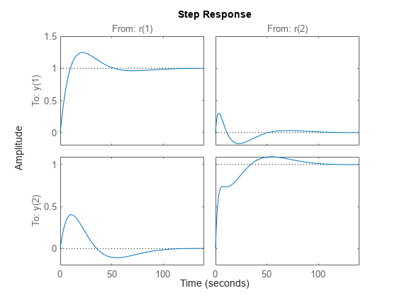
調整された係数で制御システムの時間領域応答をチェックします。プロットを作成するには、調整後の制御システムの閉ループ モデルを作成します。参照から出力までのステップ応答をプロットします。
T = connect(G,C,'r','y');
step(T)

コントローラーの分離行列では、2 チャネル出力信号 y の各チャネルが、最小のクロストークで基準信号 r の対応するチャネルを追従できます。プロットから、帯域幅のみに対して制御システムを調整した場合にこの要件がどれだけよく達成されるか把握できます。クロストークが設計要件を超えている場合でも、TuningGoal.Gain 要件オブジェクトを使用して、調整にさらに制限を加えることができます。
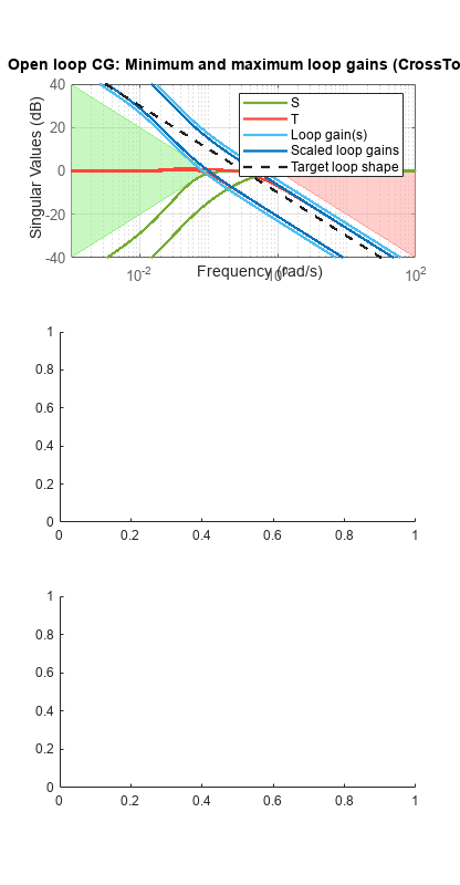
調整後のコントローラーの他の検証方法として調整後の結果の周波数領域応答を調べます。
figure('Position',[100,100,520,1000])
loopview(G,C,Info)
最初のプロットは、開ループ ゲインの交差が指定された間隔 [0.1,1] 内であることを示しています。このプロットには、感度関数 および相補感度 の最大値と調整値も含まれます。2 つ目と 3 つ目のプロットには、調整後のシステムの MIMO 安定余裕 (青い曲線) が上限 (黄色の曲線) を超えていないことが示されています。