空間多重化
この例は空間多重化方式を示します。ここでは、データ ストリームがそれぞれ独立なサブストリームに分割され、それぞれが各送信アンテナに利用されます。結果として、これらのスキームでは多重化ゲインを提供しますが、空間時間ブロック符号化に必要な明示的な直交化は不要です。
空間多重化では、受信側で高度な復号化技術が必要になります。多数の推奨技術のうち [1]、この例では、2 つの逐次干渉キャンセラ (SIC) 検出スキームに注目します。これらのスキームは [ 2 ]、[ 3 ] における元のベル研究所の層別空間時間 (BLAST) 技術と似ています。
説明するうえで便利なため、この例では 2 本の送信アンテナと 2 本の受信アンテナを採用している基本的な 2x2 MIMO システムを使用します。符号化されていない QPSK 変調システムでは、個々の送受信リンクではなく、フラットなレイリー フェージングを使用します。受信端では、開ループ空間多重化システムなど、送信側へのフィードバックのない、チャネルの完全な把握がなされているものと仮定します。
この例では、シンボルのキャンセルをもつ 2 つの非線形干渉キャンセラ メソッドであるゼロフォーシング (ZF) と最小平均二乗誤差 (MMSE) を示し、それらの性能を最尤 (ML) 最適受信側と比較します。
シミュレーション
共通のシミュレーション パラメーターを定義し、シミュレーションをセットアップします。
N = 2;           % Number of transmit antennas
M = 2;           % Number of receive antennas
EbNoVec = 2:3:8; % Eb/No in dB
bps = 2;         % Bits per symbol
M = 2^bps;       % Constellation size
再現性をもたせるために、乱数発生器が使用するローカルの乱数ストリームを作成します。
stream = RandStream('mt19937ar');

% Calculate SNR from EbNo for each independent transmission link
snrIndB = convertSNR(EbNoVec,'ebno','BitsPerSymbol',bps);
snrLinear = 10.^(0.1*snrIndB);

% Create error rate calculation System objects for 3 different receivers
zfBERCalc = comm.ErrorRate;
mmseBERCalc = comm.ErrorRate;
mlBERCalc = comm.ErrorRate;

% Get all bit and symbol combinations for ML receiver
allBits = int2bit(0:2^(bps*N)-1,bps*N);
allTxSig = reshape(pskmod(allBits(:),M,0,InputType="bit"), ...
    N,2^(bps*N));

% Pre-allocate variables to store BER results for speed
[BER_ZF,BER_MMSE,BER_ML] = deal(zeros(length(EbNoVec),3));
下のシミュレーション ループは、同じデータとチャネルを使用して、それぞれの Eb/No 値の 3 つの受信スキームの BER 性能を評価します。シミュレーションのため、Eb/No を狭いレンジで評価します。同じコードを使用した、広レンジ シミュレーションの結果は後述します。
% Set up a figure for visualizing BER results
fig = figure;
grid on;
hold on;
ax = fig.CurrentAxes;
ax.YScale = 'log';
xlim([EbNoVec(1)-0.01 EbNoVec(end)]);
ylim([1e-3 1]);
xlabel('Eb/No (dB)');
ylabel('BER');
fig.NumberTitle = 'off';
fig.Name = 'Spatial Multiplexing';
title('2x2 Uncoded QPSK System');
set(fig,'DefaultLegendAutoUpdate','off');

% Loop over selected EbNo points
for idx = 1:length(EbNoVec)
    % Reset error rate calculation System objects
    reset(zfBERCalc);
    reset(mmseBERCalc);
    reset(mlBERCalc);

    while (BER_ZF(idx, 3) < 1e5) && ((BER_MMSE(idx, 2) < 100) || ...
          (BER_ZF(idx, 2) < 100) || (BER_ML(idx, 2) < 100))
        % Create random bit vector to modulate
        msg = randi(stream,[0 1],[N*bps,1]);

        % Modulate data
        txSig = pskmod(msg,M,0,InputType="bit");

        % Flat Rayleigh fading channel with independent links
        rayleighChan = (randn(stream,M,N) + 1i*randn(stream,M,N))/sqrt(2);

        % Add noise to faded data
        rxSig = awgn(rayleighChan*txSig,snrIndB(idx),0,stream);

        % ZF-SIC receiver
        r = rxSig;
        H = rayleighChan; % Assume perfect channel estimation
        % Initialization
        estZF = zeros(N*bps,1);
        orderVec = 1:N;
        k = N+1;
        % Start ZF nulling loop
        for n = 1:N
            % Shrink H to remove the effect of the last decoded symbol
            H = H(:,[1:k-1,k+1:end]);
            % Shrink order vector correspondingly
            orderVec = orderVec(1,[1:k-1,k+1:end]);
            % Select the next symbol to be decoded
            G = (H'*H) \ eye(N-n+1); % Same as inv(H'*H), but faster
            [~, k] = min(diag(G));
            symNum = orderVec(k);

            % Hard decode the selected symbol
            decBits = pskdemod(G(k,:) * H' * r,M,0,OutputType="bit");
            estZF(bps * (symNum-1) + (1:bps)) = decBits;

            % Subtract the effect of the last decoded symbol from r
            if n < N
                r = r - H(:, k) * pskmod(decBits,M,0,InputType="bit");
            end
        end

        % MMSE-SIC receiver
        r = rxSig;
        H = rayleighChan;
        % Initialization
        estMMSE = zeros(N*bps, 1);
        orderVec = 1:N;
        k = N+1;
        % Start MMSE nulling loop
        for n = 1:N
            H = H(:, [1:k-1,k+1:end]);
            orderVec = orderVec(1, [1:k-1,k+1:end]);
            % Order algorithm (matrix G calculation) is the only difference
            % with the ZF-SIC receiver
            G = (H'*H + ((N-n+1)/snrLinear(idx))*eye(N-n+1)) \ eye(N-n+1);
            [~, k] = min(diag(G));
            symNum = orderVec(k);

            decBits = pskdemod(G(k,:) * H' * r,M,0,OutputType="bit");
            estMMSE(bps * (symNum-1) + (1:bps)) = decBits;

            if n < N
                r = r - H(:, k) * pskmod(decBits,M,0,InputType="bit");
            end
        end

        % ML receiver
        r = rxSig;
        H = rayleighChan;
        [~, k] = min(sum(abs(repmat(r,[1,2^(bps*N)]) - H*allTxSig).^2));
        estML = allBits(:,k);

        % Update BER
        BER_ZF(idx,:) = zfBERCalc(msg,estZF);
        BER_MMSE(idx,:) = mmseBERCalc(msg,estMMSE);
        BER_ML(idx,:) = mlBERCalc(msg,estML);
    end

    % Plot results
    semilogy(EbNoVec(1:idx),BER_ZF(1:idx,1),'r*', ...
             EbNoVec(1:idx),BER_MMSE(1:idx,1),'bo', ...
             EbNoVec(1:idx),BER_ML(1:idx,1),'gs');
    legend('ZF-SIC','MMSE-SIC','ML');
    drawnow;
end

% Draw the lines
semilogy(EbNoVec,BER_ZF(:,1),'r-', ...
         EbNoVec,BER_MMSE(:,1),'b-', ...
         EbNoVec,BER_ML(:,1),'g-');
hold off;

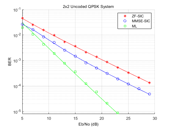
[ 4 ] でわかるように、性能が最も優れているのは ML 受信機、次は MMSE-SIC および ZF-SIC 受信機です。受信機の複雑度に関しては、ML は、送信アンテナの数と共に指数的に大きくなります。一方、ZF-SIC および MMSE-SIC は、逐次干渉キャンセラと組み合わされた線形受信機です。複雑さを減らすために最適化された ZF-SIC および MMSE-SIC アルゴリズムは、[ 5 ] に記載されています。
Eb/No 値がもっと広い範囲の 3 つのスキームを比較したシミュレーション結果を、以下に示します。これらの曲線により、BER 曲線の傾きから得られるダイバーシティ次数を測定することができます。
openfig('spatMuxResults.fig');

その他の評価例としては、チャネル推定がある場合とない場合でアンテナ数を増加してこれらの手法を試すことが挙げられます。
参考文献
George Tsoulos, Ed., "MIMO System Technology for Wireless Communications", CRC Press, Boca Raton, FL, 2006.
G. J. Foschini, "Layered space-time architecture for wireless communication in a fading environment when using multiple antennas," The Bell Sys.Tech. Journal, 1996, No. 1, pp. 41-59.
P. W. Wolniansky, G. J. Foschini, G. D. Golden, R. A. Valenzuela, "V-BLAST: An Architecture for realizing very high data rates over the rich scattering wireless channel," 1998 URSI International Symposium on Signals, Systems, and Electronics, 29 Sep.-2 Oct. 1998, pp. 295-300.
X. Li, H. C. Huang, A. Lozano, G. J. Foschini, "Reduced-complexity detection algorithms for systems using multi-element arrays", IEEE® Global Telecommunications Conference, 2000. Volume 2, 27 Nov.-1 Dec. 2000, pp. 1072-76.
Y. Shang and X.-G. Xia, "On fast recursive algorithms for V-BLAST with optimal ordered SIC detection," IEEE Trans. Wireless Communications, vol. 8, no. 6, pp. 2860-2865, Jun. 2009.