ACPR Measurements Using WCDMA Signal
This example shows you how to obtain adjacent channel power ratio (ACPR) measurements using a WCDMA communications signal, according to the 3GPP™ TS 125.104 standard [1].
ACPR calculations characterize spectral regrowth in a communications systems component, such as a modulator or an analog front end. Amplifier nonlinearity causes spectral regrowth. ACPR calculations determine the likelihood that a given system causes interference with an adjacent channel. Most standards define ACPR measurements as the ratio of the average power in the main channel and any adjacent channels. The offset frequencies and measurement bandwidths (BWs) you use when obtaining measurements depend on which specific industry standard you are using. For instance, measurements for CDMA amplifiers involve two offsets (from the carrier frequency) of 885 kHz and 1.98 MHz, and a measurement BW of 30 KHz.
In this example, you use the comm.ACPR System object to measure the ACPR of a WCDMA signal.
Create System Object and Set Up Measurements
Define the sample rate, load the WCDMA file, and get the data.
% System sampling frequency, 3.84 MHz chip rate, 8 samples per chip
SampleRate = 3.84e6*8;
load WCDMASignal2.mat
% Use the first signal snapshot
txSignalBeforeAmplifier = dataBeforeAmplifier(:,1);
txSignalAfterAmplifier = dataAfterAmplifier(:,1);
Create the comm.ACPR System object and specify the sampling frequency.
acprAmpIn = comm.ACPR('SampleRate',SampleRate)acprAmpIn =
comm.ACPR with properties:
NormalizedFrequency: false
SampleRate: 30720000
MainChannelFrequency: 0
MainMeasurementBandwidth: 50000
AdjacentChannelOffset: [-100000 100000]
AdjacentMeasurementBandwidth: 50000
MeasurementFilterSource: 'None'
SpectralEstimation: 'Auto'
FFTLength: 'Next power of 2'
MaxHold: false
PowerUnits: 'dBm'
MainChannelPowerOutputPort: false
AdjacentChannelPowerOutputPort: false
Specify the main channel center frequency using the MainChannelFrequency property. Then, specify the main channel measurement bandwidth using the MainMeasurementBandwidth property.
For the baseband data, the main channel center frequency is at 0 Hz. The WCDMA standard specifies to obtain main channel power using a 3.84 MHz measurement bandwidth.
acprAmpIn.MainChannelFrequency = 0;
acprAmpIn.MainMeasurementBandwidth = 3.84e6;
Specify adjacent channel offsets and measurement bandwidths.
The WCDMA standard specifies ACPR limits for four adjacent channels, located at 5, –5, 10, –10 MHz away from the main channel center frequency. In all cases, obtain adjacent channel power using a 3.84-MHz bandwidth. Specify the adjacent channel offsets and measurement bandwidths using the AdjacentChannelOffset and AdjacentMeasurementBandwidth properties.
acprAmpIn.AdjacentChannelOffset = [-10 -5 5 10]*1e6;
acprAmpIn.AdjacentMeasurementBandwidth = 3.84e6;
If the measurement bandwidths for all the adjacent channels are equal, specify a scalar value. If the measurement bandwidths are different, specify a vector of measurement bandwidths with a length equal to the length of the offset vector.
Set the MainChannelPowerOutputPort and AdjacentChannelPowerOutputPort properties to true.
acprAmpIn.MainChannelPowerOutputPort = true
acprAmpIn =
  comm.ACPR with properties:

               NormalizedFrequency: false
                        SampleRate: 30720000
              MainChannelFrequency: 0
          MainMeasurementBandwidth: 3840000
             AdjacentChannelOffset: [-10000000 -5000000 5000000 10000000]
      AdjacentMeasurementBandwidth: 3840000
           MeasurementFilterSource: 'None'
                SpectralEstimation: 'Auto'
                         FFTLength: 'Next power of 2'
                           MaxHold: false
                        PowerUnits: 'dBm'
        MainChannelPowerOutputPort: true
    AdjacentChannelPowerOutputPort: false
acprAmpIn.AdjacentChannelPowerOutputPort = true
acprAmpIn =
  comm.ACPR with properties:

               NormalizedFrequency: false
                        SampleRate: 30720000
              MainChannelFrequency: 0
          MainMeasurementBandwidth: 3840000
             AdjacentChannelOffset: [-10000000 -5000000 5000000 10000000]
      AdjacentMeasurementBandwidth: 3840000
           MeasurementFilterSource: 'None'
                SpectralEstimation: 'Auto'
                         FFTLength: 'Next power of 2'
                           MaxHold: false
                        PowerUnits: 'dBm'
        MainChannelPowerOutputPort: true
    AdjacentChannelPowerOutputPort: true
Create a comm.ACPR System object to measure the amplifier output.
acprAmpOut = clone(acprAmpIn);
Obtain ACPR Measurements
The object returns the ACPR measurements, and can return power measurements for the main and adjacent channels. The PowerUnits property specifies the unit of measure. The property value defaults to dBm (power ratio referenced to 1 mW.
Obtain the ACPR measurements at the amplifier input:
[ACPR,mainChanPwr,adjChanPwr] = ...
    acprAmpIn(txSignalBeforeAmplifier)
ACPR = 1×4
-68.6668 -54.9002 -55.0653 -68.4604
mainChanPwr =
29.5190
adjChanPwr = 1×4

  -39.1477  -25.3812  -25.5463  -38.9414
Obtain the ACPR measurements at the amplifier output:
[ACPR,mainChanPwr,adjChanPwr] = ...
    acprAmpOut(txSignalAfterAmplifier)
ACPR = 1×4
-42.1625 -27.0912 -26.8785 -42.4915
mainChanPwr =
40.6725
adjChanPwr = 1×4

   -1.4899   13.5813   13.7941   -1.8190
Notice the increase in ACPR values at the output of the amplifier. This increase reflects distortion due to amplifier nonlinearity. The WCDMA standard specifies that ACPR values be below -45 dB at +/–5 MHz offsets, and below –50 dB at +/–10 MHz offsets. In this example, the signal at the amplifier input meets the specifications while the signal at the amplifier output does not.
Specify Measurement Filter
The WCDMA standard specifies to obtain ACPR measurements using a root-raised-cosine filter. It also states to measure both the main channel power and the adjacent channel powers using a matched root-raised-cosine (RRC) filter with roll-off factor 0.22. You specify the measurement filter by using the MeasurementFilter property. This property value defaults to an all-pass filter with unity gain.
The filter must be an FIR filter, and its response must center at 0 Hz. The ACPR object automatically shifts and applies the filter at each of the specified main and adjacent channel bands. (The power measurement still falls within the bands specified by the MainMeasurementBandwidth, and AdjacentMeasurementBandwidth properties.)
The WCDMASignal.mat file contains data that was obtained using a 96 tap filter with a roll-off factor of 0.22.
Create the filter and obtain measurements using the rcosdesign function.
% Scale for 0 dB passband gain
measFilt = rcosdesign(0.22,16,8)/sqrt(8);
Set that filter as the measurement filter for the ACPR object.
release(acprAmpIn);
acprAmpIn.MeasurementFilterSource = 'Property';
acprAmpIn.MeasurementFilter = measFilt;
Implement the same filter at the amplifier output by cloning the comm.ACPR System object.
acprAmpOut = clone(acprAmpIn)
acprAmpOut =
  comm.ACPR with properties:

               NormalizedFrequency: false
                        SampleRate: 30720000
              MainChannelFrequency: 0
          MainMeasurementBandwidth: 3840000
             AdjacentChannelOffset: [-10000000 -5000000 5000000 10000000]
      AdjacentMeasurementBandwidth: 3840000
           MeasurementFilterSource: 'Property'
                 MeasurementFilter: [-5.9574e-04 -2.9323e-04 9.2510e-05 4.8190e-04 7.8966e-04 9.4357e-04 9.0157e-04 6.6302e-04 2.7143e-04 -1.9278e-04 -6.2825e-04 -9.3454e-04 -0.0010 -8.9730e-04 -5.4141e-04 -4.1308e-05 4.8972e-04 … ] (1×129 double)
                SpectralEstimation: 'Auto'
                         FFTLength: 'Next power of 2'
                           MaxHold: false
                        PowerUnits: 'dBm'
        MainChannelPowerOutputPort: true
    AdjacentChannelPowerOutputPort: true
Obtain the ACPR power measurements at the amplifier input.
ACPR = acprAmpIn(txSignalBeforeAmplifier)
ACPR = 1×4

  -71.4648  -55.5514  -55.9476  -71.3909
Obtain the ACPR power measurements at the amplifier output.
ACPRoutput = acprAmpOut(txSignalAfterAmplifier)
ACPRoutput = 1×4

  -42.2364  -27.2242  -27.0748  -42.5810
Enable Estimator Properties
By default, the ACPR object measures power using a Welch power spectral estimator with a Hamming window and zero percent overlap. The object uses a rectangle approximation of the integral for the power spectral density estimates in the measurement bandwidth of interest. If you set SpectralEstimation to 'Specify Window Parameters' several properties become available, providing you control of the resolution, variance, and dynamic range of the spectral estimates.
Enable the SegmentLength, OverlapPercentage, and WindowOption properties.
release(acprAmpOut)
acprAmpOut.SpectralEstimation = 'Specify window parameters'
acprAmpOut =
comm.ACPR with properties:
NormalizedFrequency: false
SampleRate: 30720000
MainChannelFrequency: 0
MainMeasurementBandwidth: 3840000
AdjacentChannelOffset: [-10000000 -5000000 5000000 10000000]
AdjacentMeasurementBandwidth: 3840000
MeasurementFilterSource: 'Property'
MeasurementFilter: [-5.9574e-04 -2.9323e-04 9.2510e-05 4.8190e-04 7.8966e-04 9.4357e-04 9.0157e-04 6.6302e-04 2.7143e-04 -1.9278e-04 -6.2825e-04 -9.3454e-04 -0.0010 -8.9730e-04 -5.4141e-04 -4.1308e-05 4.8972e-04 … ] (1×129 double)
SpectralEstimation: 'Specify window parameters'
SegmentLength: 64
OverlapPercentage: 0
Window: 'Hamming'
FFTLength: 'Next power of 2'
MaxHold: false
PowerUnits: 'dBm'
MainChannelPowerOutputPort: true
AdjacentChannelPowerOutputPort: true
This change allows you to customize the spectral estimates for obtaining power measurements. For example, you can the spectral estimator segment length to 1024 and increase the overlap percentage to 50 percent, reducing the consequent variance increase. You can also choose a window with larger side lobe attenuation (compared to the default Hamming window).
Create a spectral estimator with a Chebyshev window and a side lobe attenuation of 200 dB. Choosing a Chebyshev window enables a SidelobeAttenuation property to set the side lobe attenuation of the window.
acprAmpOut.SegmentLength = 1024;
acprAmpOut.OverlapPercentage = 50;
acprAmpOut.Window = 'Chebyshev';
acprAmpOut.SidelobeAttenuation = 200;
Obtain the ACPR power measurements at the amplifier output.
ACPRoutput = acprAmpOut(txSignalAfterAmplifier)
ACPRoutput = 1×4

  -44.9399  -30.7136  -30.7670  -44.4450
Measure Power Using Max-Hold Option
Some communications standards specify using max-hold spectrum power measurements when computing ACPR values. Such calculations compare the current power spectral density vector estimation to the previous max-hold accumulated power spectral density vector estimation. When taking max-hold measurements, the object obtains the power spectral density vector estimation using the current input data. It obtains the previous max-hold accumulated power spectral density vector from the previous call to the object. The object uses the maximum values at each frequency bin for calculating average power measurements. A call to the reset method clears the max-hold spectrum.
Accumulate max-hold spectra for 21 amplifier output data snapshots and get ACPR measurements.
for idx = 1:21
    acprAmpOut(dataAfterAmplifier(:,idx));
end
ACPRoutput = acprAmpOut(dataAfterAmplifier(:,21))
ACPRoutput = 1×4

  -43.7422  -27.5056  -28.1154  -43.4043
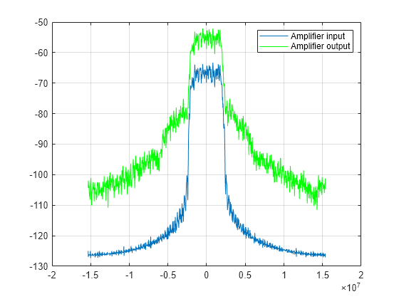
Plot Signal Spectrum
Plot the power spectral density of the WCDMA signals at the input and output of the nonlinear amplifier. The plot allows you to visualize the spectral regrowth effects intrinsic to amplifier nonlinearity. The measurements reflect the spectral regrowth.
win = hamming(1024);
[PSD1,F] = pwelch(txSignalBeforeAmplifier, ...
    win,50,1024,SampleRate,'centered');
[PSD2,F] = pwelch(txSignalAfterAmplifier, ...
    win,50,1024,SampleRate,'centered');
plot(F,10*log10(PSD1))
hold on
grid on
plot(F,10*log10(PSD2),'g')
legend('Amplifier input','Amplifier output')
References
[1] 3GPP.TS.25.104. 3rd Generation Partnership Project; Technical Specification Group Radio Access Network "Base Station (BS) radio transmission and reception (FDD)"