CSI-RS を使用した NR チャネル推定
この例では、TS 38.211 の Section 7.4.1.5 で定義されているように、指定されたキャリアと CSI-RS リソース構成に対してチャネル状態情報基準信号 (CSI-RS) のシンボルとインデックスを生成する方法を説明します。この例では、生成したシンボルをキャリア リソース グリッドにマッピングし、受信機側でチャネル推定を実行して、推定したチャネルと実際のチャネルを比較する方法を説明します。
はじめに
CSI-RS は、ダウンリンク固有 (DL) の基準信号です。NR 規格では、ゼロ電力 (ZP) と非ゼロ電力 (NZP) の CSI-RS を定義しています。
ユーザー端末 (UE) 処理では、次について NZP-CSI-RS を利用します。
移動とビーム管理のための L1 基準信号受信電力 (RSRP) の測定
DL CSI の取得
干渉測定
時間と周波数のトラッキング
ZP-CSI-RS は、DL CSI の取得と干渉測定に使用されます。さらに、特定のリソース エレメント (RE) をマスクして、PDSCH 送信に利用できないようにします。ZP という名前が示すように、それらの RE では何も送信されません。
この例では、CSI-RS を使用して、CSI 取得の基礎となるチャネル推定を実行する方法を説明します。
構成オブジェクトの初期化
15 kHz のサブキャリア間隔で 5 MHz のキャリアを表すキャリア構成オブジェクトを作成します。
carrier = nrCarrierConfig;
carrier.NSizeGrid = 25;
carrier.SubcarrierSpacing = 15;
carrier.NSlot = 1;
carrier.NFrame = 0
carrier =
  nrCarrierConfig with properties:

                NCellID: 1
      SubcarrierSpacing: 15
           CyclicPrefix: 'normal'
              NSizeGrid: 25
             NStartGrid: 0
                  NSlot: 1
                 NFrame: 0
    IntraCellGuardBands: [0×2 double]

   Read-only properties:
         SymbolsPerSlot: 14
       SlotsPerSubframe: 1
          SlotsPerFrame: 10
2 つの CSI-RS リソース (行番号 3 の NZP と行番号 5 の ZP) を表す CSI-RS 構成オブジェクトを作成します。
csirs = nrCSIRSConfig;
csirs.CSIRSType = {'nzp','zp'};
csirs.CSIRSPeriod = {[5 1],[5 1]};
csirs.Density = {'one','one'};
csirs.RowNumber = [3 5];
csirs.SymbolLocations = {1,6};
csirs.SubcarrierLocations = {6,4};
csirs.NumRB = 25
csirs =
nrCSIRSConfig with properties:
CSIRSType: {'nzp' 'zp'}
CSIRSPeriod: {[5 1] [5 1]}
RowNumber: [3 5]
Density: {'one' 'one'}
SymbolLocations: {[1] [6]}
SubcarrierLocations: {[6] [4]}
NumRB: 25
RBOffset: 0
NID: 0
Read-only properties:
NumCSIRSPorts: [2 4]
CDMType: {'FD-CDM2' 'FD-CDM2'}
dB 単位での CSI-RS のパワー スケーリングを確認します。
powerCSIRS = 0;
disp(['CSI-RS power scaling: ' num2str(powerCSIRS) ' dB']);
CSI-RS power scaling: 0 dB
CSI-RS シンボルとインデックスの生成
指定したキャリアと CSI-RS 構成パラメーターについて CSI-RS シンボルを生成します。パワー スケーリングを適用します。
sym = nrCSIRS(carrier,csirs);
csirsSym = sym*db2mag(powerCSIRS);
変数 csirsSym は、CSI-RS シンボルを含む列ベクトルです。
指定したキャリアと CSI-RS 構成パラメーターについて CSI-RS インデックスを生成します。
csirsInd = nrCSIRSIndices(carrier,csirs);
変数 csirsInd も、csirsSym と同じサイズの列ベクトルです。
ZP と NZP の両方のリソースを構成する場合、ZP 信号の生成が NZP 信号の生成よりも優先されます。
キャリア グリッドの初期化
1 スロット分のキャリア リソース グリッドを初期化します。
ports = max(csirs.NumCSIRSPorts);   % Number of antenna ports
txGrid = nrResourceGrid(carrier,ports);
キャリア グリッドへの CSI-RS シンボルのマッピング
リソース エレメントのマッピングを実行します。
txGrid(csirsInd) = csirsSym;
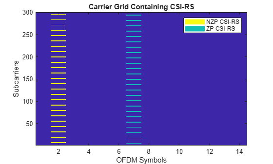
CSI-RS (ZP と NZP の両方) の位置をグリッドにプロットします。
plotGrid(size(txGrid),csirsInd,csirsSym);
OFDM 変調の実行
OFDM 変調を実行し、時間領域の波形を生成します。
[txWaveform,ofdmInfo] = nrOFDMModulate(carrier,txGrid);
時間領域波形のチャネル通過および AWGN ノイズの付加
受信アンテナの本数を構成します。
R = 4;
チャネルを構成します。
channel = nrTDLChannel;
channel.NumTransmitAntennas = ports;
channel.NumReceiveAntennas = R;
channel.DelayProfile = 'TDL-C';
channel.MaximumDopplerShift = 10;
channel.DelaySpread = 1e-8;
チャネルのサンプル レートを設定します。
waveformInfo = nrOFDMInfo(carrier);
channel.SampleRate = waveformInfo.SampleRate
channel =
  nrTDLChannel with properties:

                 DelayProfile: 'TDL-C'
                  DelaySpread: 1.0000e-08
          MaximumDopplerShift: 10
                   SampleRate: 7680000
           PathGainSampleRate: 'signal'
              MIMOCorrelation: 'Low'
                 Polarization: 'Co-Polar'
        TransmissionDirection: 'Downlink'
          NumTransmitAntennas: 4
           NumReceiveAntennas: 4
           NormalizePathGains: true
                  InitialTime: 0
                 NumSinusoids: 48
                 RandomStream: 'mt19937ar with seed'
                         Seed: 73
      NormalizeChannelOutputs: true
             ChannelFiltering: true
    TransmitAndReceiveSwapped: false
        ChannelResponseOutput: 'path-gains'
構成されたチャネルに基づいて、チャネル遅延を適用し、送信波形にゼロを付加します。
chInfo = info(channel);
maxChDelay = chInfo.MaximumChannelDelay;
txWaveform = [txWaveform; zeros(maxChDelay,size(txWaveform,2))];
チャネル経由で波形を渡します。
[rxWaveform,pathGains] = channel(txWaveform);
実際の伝播チャネル H_actual を生成するには、完全なチャネル推定を実行します。
pathFilters = getPathFilters(channel);
H_actual = nrPerfectChannelEstimate(carrier,pathGains,pathFilters);
AWGN ノイズを波形に付加します。この例で使用している SNR 定義の説明については、リンク シミュレーションで使用する SNR の定義を参照してください。
SNRdB = 50;           % in dB
SNR = 10^(SNRdB/10);  % Linear value
N0 = 1/sqrt(2.0*R*double(ofdmInfo.Nfft)*SNR); % Noise variance
rng(0);
noise = N0*complex(randn(size(rxWaveform)),randn(size(rxWaveform)));
rxWaveform = rxWaveform + noise;
NZP-CSI-RS を使用して、タイミング同期を実行します。タイミング オフセットを推定するために、nrTimingEstimate を使用し、NZP-CSI-RS を基準と見なします。
% Disable ZP-CSI-RS resource, not going to be used for timing and channel
% estimation
csirs.CSIRSPeriod = {[5 1],'off'};
% Generate reference symbols and apply power scaling
refSym = db2mag(powerCSIRS)*nrCSIRS(carrier,csirs);
% Generate reference indices
refInd = nrCSIRSIndices(carrier,csirs);
offset = nrTimingEstimate(carrier,rxWaveform,refInd,refSym)
offset =
7
rxWaveform = rxWaveform(1+offset:end,:);
時間領域の受信波形を OFDM 復調します。
rxGrid = nrOFDMDemodulate(carrier,rxWaveform); % Of size K-by-L-by-R推定チャネルと実際のチャネルの比較
NZP-CSI-RS を使用して、実用的なチャネル推定を実行します。CSI-RS シンボル csirsSym の CDM タイプが同じであることを確認します。
cdmLen = [2 1]; % Corresponds to CDMType = 'FD-CDM2'
[H_est,nVar] = nrChannelEstimate(carrier,rxGrid,refInd,refSym,'CDMLengths',cdmLen);
disp(['Estimated noise variance = ' num2str(nVar)])
Estimated noise variance = 0.00011155
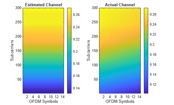
最初の送信アンテナと最初の受信アンテナの間の推定チャネルと実際のチャネルをプロットします。
figure;

% Plot the estimated channel
subplot(1,2,1)
imagesc(abs(H_est(:,:,1,1)));
colorbar;
title('Estimated Channel')
axis xy;
xlabel('OFDM Symbols');
ylabel('Subcarriers');

% Plot the actual channel
subplot(1,2,2)
imagesc(abs(H_actual(:,:,1,1)));
colorbar;
title('Actual Channel')
axis xy;
xlabel('OFDM Symbols');
ylabel('Subcarriers');
チャネル推定誤差を計算します。
H_err = (H_est - H_actual(:,:,:,1:size(H_est,4)));
[minErr,maxErr] = bounds(abs(H_err),'all');
disp(['Absolute value of the channel estimation error is in the range of [' num2str(minErr) ', ' num2str(maxErr) ']'])
Absolute value of the channel estimation error is in the range of [2.4865e-05, 0.029678]
ローカル関数
function plotGrid(gridSize,csirsInd,csirsSym)
%    plotGrid(GRIDSIZE,CSIRSIND,CSIRSSYM) plots the carrier grid of size GRIDSIZE
%    by populating the grid with CSI-RS symbols using CSIRSIND and CSIRSSYM.

    figure()
    cmap = colormap(gcf);
    chpval = {20,2};
    chpscale = 0.25*length(cmap); % Scaling factor

    tempSym = csirsSym;
    tempSym(tempSym ~= 0) = chpval{1}; % Replacing non-zero-power symbols
    tempSym(tempSym == 0) = chpval{2}; % Replacing zero-power symbols
    tempGrid = complex(zeros(gridSize));
    tempGrid(csirsInd) = tempSym;

    image(chpscale*tempGrid(:,:,1)); % Multiplied with scaling factor for better visualization
    axis xy;
    names = {'NZP CSI-RS','ZP CSI-RS'};
    clevels = chpscale*[chpval{:}];
    N = length(clevels);
    L = line(ones(N),ones(N),'LineWidth',8); % Generate lines
    % Index the color map and associate the selected colors with the lines
    set(L,{'color'},mat2cell(cmap( min(1+clevels,length(cmap) ),:),ones(1,N),3)); % Set the colors according to cmap
    % Create legend
    legend(names{:});

    title('Carrier Grid Containing CSI-RS')
    xlabel('OFDM Symbols');
    ylabel('Subcarriers');
end
参照
[1] 3GPP TS 38.211. “NR; Physical channels and modulation.” 3rd Generation Partnership Project; Technical Specification Group Radio Access Network.