Wi-Fi 8 Waveform Generation
This example shows how to parameterize and generate IEEE® 802.11bn™ ultra high reliability (UHR) multi-user waveforms.
Introduction
The physical layer of the IEEE P802.11bn/D1.0 draft standard [1] is an extension of 802.11be™ (Wi-Fi® 7) [2] and focuses on WLAN indoor and outdoor operations. The Wi-Fi 8 standard focuses on reliability instead of speed [1]. UHR devices coexist with legacy 802.11-compliant devices that operate in the 2.4, 5, and 6 GHz unlicensed spectra. The IEEE P802.11bn/D1.0 [1] specifies three PPDU formats.
UHR MU (multi-user)
UHR TB (trigger-based)
UHR ELR (enhanced long range)
The UHR MU packet enables OFDMA or non-OFDMA transmission. A UHR MU packet can transmit to a single user over the whole band, multiple users over different parts of the band (OFDMA), or multiple users over the same part of the band (MU-MIMO). This example shows how to generate a UHR MU packet for each of these different waveforms and demonstrates some of the key features of the draft standard [1] such as unequal modulation (UEQM).
The UHR TB packet enables OFDMA or MU-MIMO transmission in the uplink. The access point (AP) controls UHR TB transmissions. A trigger frame sent to all stations (STAs) participating in the transmission contains all the parameters required for the transmission. When triggered by the AP, each STA simultaneously transmits a UHR TB packet. This example shows how to generate a UHR TB transmission in response to a trigger frame in a combined OFDMA MU-MIMO transmission. This example also shows a TB transmission on a distributed resource unit (DRU) in response to a trigger frame in an OFDMA transmission.
The UHR ELR packet is optimized for long-range, low data rate communication. The purpose is to enable a low-speed connection over much greater distances than traditional Wi-Fi packets.
UHR MU Packet Format
As in Wi-Fi 7 transmissions, the channel bandwidth of a Wi-Fi 8 transmission is divided into RUs or MRUs. In a UHR MU transmission, the RU sizes and tones are the same as Wi-Fi 7. For more details on subcarrier and resource allocation for RUs and MRUs, see the 802.11be Waveform Generation example.
Non-OFDMA Packet Format
A full-band non-OFDMA packet is a UHR MU packet that contains the transmission of a single user or multiple users in an MU-MIMO configuration over the full channel bandwidth. The draft standard [1] defines possible sizes and locations of RUs in section 38.3.15.9. See also RU Allocation Subfield.
Single-User Packet Generation
A UHR single-user (SU) packet is a full-band, non-OFDMA transmission to a single user. Use the UHR MU configuration object uhrMUConfig to configure the transmission parameters of a full-band UHR MU packet for a single user. Create a full-band 320 MHz single-user MIMO configuration and set the transmission parameters of the user.
cfgSU = uhrMUConfig("CBW320");
numTx = 2; % Number of transmit antennas
cfgSU.NumTransmitAntennas = numTx;
cfgSU.User{1}.APEPLength = 8000; % A-MPDU length pre-EOF padding, in bytes
cfgSU.User{1}.MCS = 12;          % Modulation and coding scheme
cfgSU.User{1}.NumSpaceTimeStreams = numTx;
cfgSU.User{1}.ChannelCoding = "ldpc2x"; % Longer LDPC block length
Get the required PSDU length for the specified transmission configuration and create a random PSDU of this length for transmission.
psdu = randi([0 1],psduLength(cfgSU)*8,1,"int8");Generate the UHR MU single-user packet by using the uhrWaveformGenerator function.
tx = uhrWaveformGenerator(psdu,cfgSU); %#ok<*NASGU> % Create packetSingle-User Packet Generation with Interference Mitigation
UHR SU full-band packets support interference mitigation (IM) mode,which enables the radio to mitigate the impact of radio frequency interference from sources such as microwave ovens, Bluetooth® devices, or neighboring Wi-Fi networks. In this mode, every data OFDM symbol includes IM pilots. For a given channel bandwidth, the subcarrier positions of the IM pilots remain fixed across all OFDM symbols, and these IM pilots carry zero energy. A UHR STA may transmit a UHR PPDU with IM enabled if all of the following conditions are met:
The UHR PPDU is an SU transmission using the UHR MU PPDU
The Punctured Channel Information field in the U-SIG field is set to 0, indicating no puncturing
There is a single space-time stream
The Data field does not use UHR-MCS 15
Use the UHR MU configuration object to configure the transmission parameters of a UHR SU packet. Create a full-band 20 MHz single-user configuration.
cfgIM = uhrMUConfig('CBW20');
cfgIM.InterferenceMitigation = true; % Use interference mitigation mode
Get the required PSDU length for the specified transmission configuration and create a random PSDU of this length for transmission. Generate the UHR MU single-user packet with IM pilots by using the uhrWaveformGenerator function.
txPSDU = randi([0 1],psduLength(cfgIM)*8,1); % Generate random PSDU
tx = uhrWaveformGenerator(txPSDU,cfgIM); % SU waveform with IM pilots
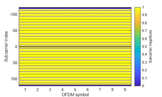
This figure shows the magnitude of data field subcarriers including the DC, guardband, data, and IM pilot subcarriers. The magnitude of IM pilot subcarriers is zero.
uhrPlotDataFieldSymbol(tx,cfgIM);
MU-MIMO Packet Generation
Configure transmission parameters for a full-band non-OFDMA UHR MU packet by using the UHR MU configuration object. Use the NumUsers property of the uhrMUConfig object to specify the number of users in an MU-MIMO configuration.
Create a 20 MHz UHR MU configuration for two users and set the parameters that are common to all users.
numTx = 2;
% Set common transmission parameters for all users
cfgMUMIMO = uhrMUConfig("CBW20",NumUsers=2);
cfgMUMIMO.NumTransmitAntennas = numTx;
cfgMUMIMO.GuardInterval = 3.2;
cfgMUMIMO.UHRLTFType = 4;
The ruInfo object function provides details of the RUs in the configuration. In this case, a single RU contains two users.
allocInfo = ruInfo(cfgMUMIMO);
disp("Allocation info:")
Allocation info:
disp(allocInfo)
                    NumUsers: 2
                      NumRUs: 1
                   RUIndices: {[1]}
                     RUSizes: {[242]}
               NumUsersPerRU: 2
    NumSpaceTimeStreamsPerRU: 2
       PowerBoostFactorPerRU: 1
                   RUNumbers: 1
                  RUAssigned: 1
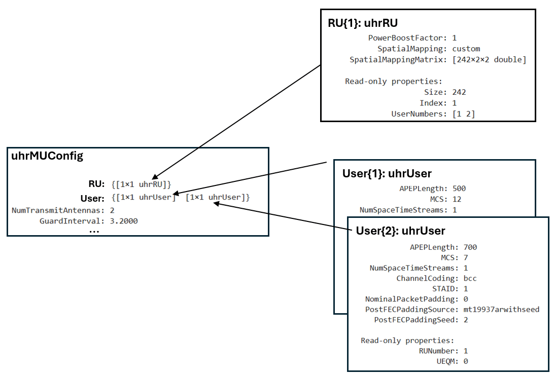
The properties of cfgMUMIMO describe the transmission configuration. The cfgMUMIMO.RU and cfgMUMIMO.User properties of cfgMUMIMO are cell arrays. Each element of the cell arrays contains an object that configures an RU or a user. When you create the cfgMUMIMO object, the elements of cfgMUMIMO.RU and cfgMUMIMO.User create the desired number of RUs and users. Each element of cfgMUMIMO.RU is a uhrRU object describing the configuration of an RU. Similarly, each element of cfgMUMIMO.User is a uhrUser object describing the configuration of a user. This figure shows the object hierarchy.
This example creates a single RU in non-OFDMA format for a channel bandwidth of 20 MHz, so cfgMUMIMO.RU is a cell array with one element. The index and size of each RU is configured according to the channel bandwidth you specified when you created cfgMUMIMO.
disp("RU configuration:")RU configuration:
disp(cfgMUMIMO.RU{1}) uhrRU with properties:
PowerBoostFactor: 1
SpatialMapping: direct
Read-only properties:
Size: 242
Index: 1
UserNumbers: [1 2]
After creating the object, you can configure each RU to create the desired transmission configuration by setting the properties of the appropriate RU object. For example, you can configure the spatial mapping and power boost factor of each RU.
Create a random spatial mapping array and specify RU index 1.
ruIndex = 1;
ofdmInfo = uhrOFDMInfo("UHR-Data",cfgMUMIMO,ruIndex);
numST = ofdmInfo.NumTones; % Number of occupied subcarriers
numSTS = allocInfo.NumSpaceTimeStreamsPerRU(ruIndex);
cfgMUMIMO.RU{ruIndex}.SpatialMapping = "Custom";
cfgMUMIMO.RU{ruIndex}.SpatialMappingMatrix = rand(numST,numSTS,numTx);
The NumUsers property of allocInfo specifies two users in the transmission, so cfgMUMIMO.User contains two elements. You can configure the transmission properties of users by modifying individual user objects. The MCS, APEP length, and channel coding scheme are examples of such properties.
Set transmission properties of user 1.
cfgMUMIMO.User{1}.APEPLength = 500; % A-MPDU length pre-EOF padding in bytes
cfgMUMIMO.User{1}.MCS = 12;
cfgMUMIMO.User{1}.ChannelCoding = "LDPC";
cfgMUMIMO.User{1}.NumSpaceTimeStreams = 1;
Set transmission properties of user 2.
cfgMUMIMO.User{2}.APEPLength = 700; % A-MPDU length pre-EOF padding in bytes
cfgMUMIMO.User{2}.MCS = 7;
cfgMUMIMO.User{2}.ChannelCoding = "BCC";
cfgMUMIMO.User{2}.NumSpaceTimeStreams = 1;
The read-only RUNumber property identifies the RU assigned to transmit this user's data.
disp("First user configuration:")First user configuration:
disp(cfgMUMIMO.User{1}) uhrUser with properties:
APEPLength: 500
MCS: 12
NumSpaceTimeStreams: 1
ChannelCoding: ldpc
STAID: 0
NominalPacketPadding: 0
PostFECPaddingSource: mt19937arwithseed
PostFECPaddingSeed: 1
Read-only properties:
RUNumber: 1
UEQM: 0
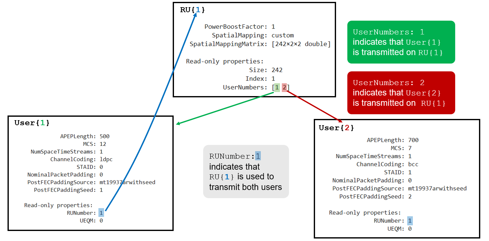
In this example, the non-OFDMA configuration consists of a single RU and two users. The UserNumbers property of an RU object indicates which users (elements of the cfgMUMIMO.User cell array) are transmitted on that RU. Similarly, the RUNumber property of each User object indicates which RU (element of the cfgMUMIMO.RU cell array) the user transmits on.
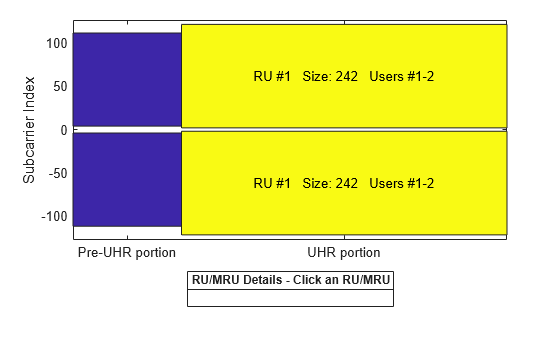
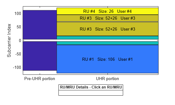
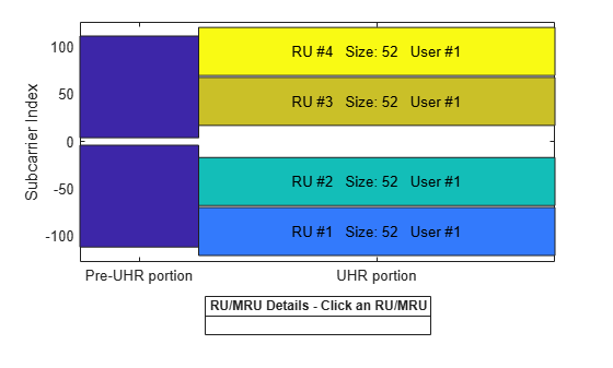
The showAllocation object function visualizes the occupied RUs or MRUs and subcarriers for the configuration you specify. The colored blocks show the occupied subcarriers in the pre-UHR and UHR portions of the packet. White indicates unoccupied subcarriers. The pre-UHR portion shows the occupied subcarriers in the fields that precede the UHR short training field (UHR-STF). The UHR portion shows the occupied subcarriers in the UHR-STF, UHR long training field (UHR-LTF), and UHR-Data fields and therefore shows the RU/MRU allocation. To display information about an RU or MRU, click on the RU or MRU. The RU number i corresponds to the ith RU element of the cfgMUMIMO.RU property. The showAllocation object function also shows the size of each RU or MRU, and the users assigned to each one. The user number j corresponds to the jth User element of the cfgMUMIMO.User property.
showAllocation(cfgMUMIMO);
To generate a non-OFDMA UHR MU waveform, create a random PSDU for each user. Since the PSDU lengths differ, use a cell array to store the PSDU for each user. The psduLength object function returns a vector with the required PSDU per user for the configuration you specified.
psduLen = psduLength(cfgMUMIMO);
psdu = cell(1,allocInfo.NumUsers);
for i = 1:allocInfo.NumUsers
    psdu{i} = randi([0 1],psduLen(i)*8,1,"int8");
end
Generate a 20 MHz non-OFDMA (MU-MIMO) packet with two users.
tx = uhrWaveformGenerator(psdu,cfgMUMIMO);
Punctured Packet Generation with Large MRUs
The draft standard allows for punctured 20 MHz subchannels in non-OFDMA or OFDMA 80, 160, or 320 MHz transmissions. Puncturing enables legacy systems to operate in the punctured subchannel. The preamble portion of the punctured 20 MHz subchannel is not transmitted and the corresponding RU is not allocated to any user (no data transmitted). This method is also known as channel bonding.
In a non-OFDMA format, large MRUs are obtained by puncturing any one of the 242-, 484-, or 996-tone RUs within an 80, 160, or 320 MHz channel. For example, you can obtain a 996+484+242-tone MRU by puncturing any one of the eight 242-tone RUs in the 160 MHz channel (see section 38.3.15.9 of [1] for more information). The preamble is not transmitted in the punctured subchannel within a large MRU and the corresponding RU is not allocated to any user. The non-OFDMA packet format supports single-user and MU-MIMO packet transmission in large MRUs. The universal signal field (U-SIG) of a UHR MU packet carries the punctured subchannel indication for a non-OFDMA transmission.
Use the UHR MU configuration object to configure the non-OFDMA transmission properties of a UHR MU packet transmission on a large MRU. Punctured Channel Information lists possible puncturing patterns for 80 MHz, 160 MHz, and 320 MHz channel bandwidths and the corresponding value of the PuncturedChannelFieldValue property when you create uhrMUConfig object.
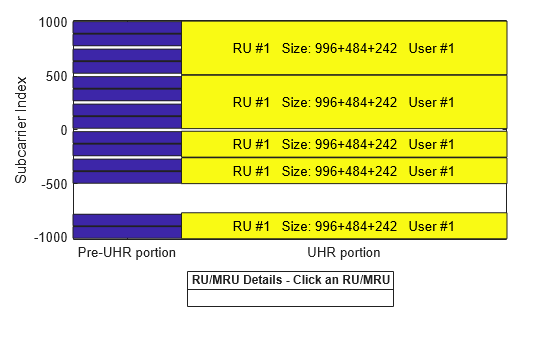
Create a configuration for a 160 MHz UHR MU packet transmission on a 996+484+242-tone MRU. Puncture the second 20 MHz subchannel in the 160 MHz channel as shown in Punctured Channel Information by setting the PuncturedChannelFieldValue property to 2.
cfgPunc = uhrMUConfig("CBW160",PuncturedChannelFieldValue=2);
tx = uhrWaveformGenerator([1 0 1 0],cfgPunc);
View the punctured RU allocation.
showAllocation(cfgPunc);
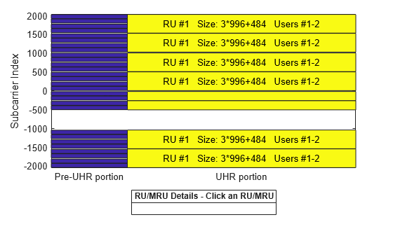
Create a configuration for two users in MU-MIMO configuration in a 320 MHz channel. The UHR MU packet transmission is on a large 3x996+484-tone MRU (see section 38.3.15.7 of [1]). Create the uhrMUConfig object, setting the PuncturedChannelFieldValue property to 3 to puncture the third 40 MHz subchannel in a 320 MHz channel as shown in Punctured Channel Information.
cfg = uhrMUConfig("CBW320",NumUsers=2,PuncturedChannelFieldValue=3);
cfg.NumTransmitAntennas = 8;
Set the transmission properties of user 1.
cfg.User{1}.NumSpaceTimeStreams = 4;
cfg.User{1}.APEPLength = 500000;
cfg.User{1}.MCS = 12;
Set the transmission properties of user 2.
cfg.User{2}.NumSpaceTimeStreams = 4;
cfg.User{2}.APEPLength = 400000;
cfg.User{2}.MCS = 13;
View the punctured RU allocation.
showAllocation(cfg);
Create a random PSDU for each user. Since the PSDU lengths differ, use a cell array to store the PSDU for each user. The psduLength object function returns a vector with the required PSDU per user for the specified configuration.
psduLen = psduLength(cfg);
allocInfo = ruInfo(cfg); % Get allocation information
psdu = cell(1,allocInfo.NumUsers);
for i=1:allocInfo.NumUsers
    psdu{i} = randi([0 1],psduLen(i)*8,1);
end
Create an oversampled waveform using the uhrWaveformGenerator function. This function generates an oversampled waveform by using a larger inverse fast Fourier transform (IFFT) size than required for the nominal baseband rate.
osf = 1.5;
tx = uhrWaveformGenerator(psdu,cfg,OversamplingFactor=osf);
Generate the spectrum and spectrogram of the generated signal. The spectrogram shows the punctured 40 MHz subchannel in the 320 MHz channel.
sa = plotSpectrumAndSpectrogram(tx,cfg,osf,"3x996+484-tone MRU with Punctured 40 MHz Subchannel in 320 MHz Channel");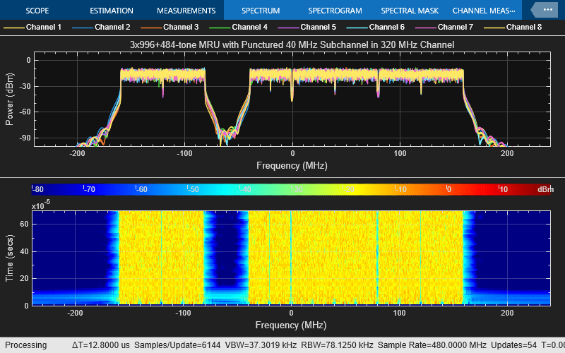
OFDMA Packet Format
The allocation index defines the assignment of RUs and MRUs in an OFDMA transmission. RU Allocation Subfield lists the allocation indices for all RU/MRU assignments. For each 20 MHz subchannel, a nine-bit index describes the number and size of RUs and MRUs and the number of users transmitted on each RU and MRU. For a whole transmission, the allocation index must be a vector of length 1, 2, 4, 8, or 16 to define the assignment for each 20 MHz subchannel in a 20, 40, 80, 160, or 320 MHz channel bandwidth, respectively. The allocation index also determines which content channel the UHR signal field (UHR-SIG) uses to signal a user.
Small MRU Packet Generation with UEQM
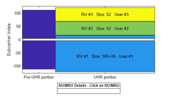
Configure transmission parameters for a UHR MU packet format in an OFDMA configuration. Create an OFDMA configuration for a 20 MHz UHR MU packet with two 52-tone RUs, one 106+26-tone MRU, and one user per RU, as defined by allocation index 47. The 106+26-tone MRU (RU 1, user 1) uses UEQM on two space-time streams. The UEQM pattern is defined in Table 38-33 [1].
cfgOFDMA = uhrMUConfig(47);
Visualize the RU allocation with the showAllocation object function.
showAllocation(cfgOFDMA)
The ruInfo object function provides details of the RUs in the configuration. There are three RUs with a user in each RU.
allocInfo = ruInfo(cfgOFDMA);
disp("Allocation info:")
Allocation info:
disp(allocInfo)
                    NumUsers: 3
                      NumRUs: 3
                   RUIndices: {[1 5]  [3]  [4]}
                     RUSizes: {[106 26]  [52]  [52]}
               NumUsersPerRU: [1 1 1]
    NumSpaceTimeStreamsPerRU: [1 1 1]
       PowerBoostFactorPerRU: [1 1 1]
                   RUNumbers: [1 2 3]
                  RUAssigned: [1 1 1]
Set common transmission parameters for all users.
numTx = 2;
cfgOFDMA.NumTransmitAntennas = numTx;
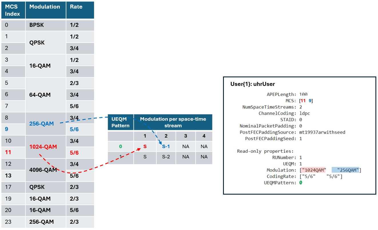
Configure RU 1 and user 1 for UEQM. To enable UEQM, you must set different modulation and coding scheme (MCS) values for each spatial stream and ensure that the coding rate is the same for all streams. For the example below, the first spatial stream uses 1024-QAM (MCS 11), while the second uses 256-QAM (MCS 9). Both MCS 11 and MCS 9 have a coding rate of 5/6. The standard [1] specifies certain allowed combinations of modulation schemes, referred to as UEQMPattern. You can check the relevant UEQM information using the read-only properties of the uhrUser object. For equal modulation (EQM), since the same MCS applies to all spatial streams, specify the MCS as a scalar. For more information on UEQM, subcarrier grouping and CSI feedback compression, see the Wi-Fi 8 Downlink Packet Error Rate Simulation Using Unequal Modulation example.
cfgOFDMA.RU{1}.SpatialMapping = "Direct";
cfgOFDMA.User{1}.APEPLength = 100;
cfgOFDMA.User{1}.MCS = [11 9]; % UEQM pattern 0 for 2 space-time streams
cfgOFDMA.User{1}.NumSpaceTimeStreams = numTx;
cfgOFDMA.User{1}.ChannelCoding = "LDPC";
Configure RU 2 and user 2.
cfgOFDMA.RU{2}.SpatialMapping = "Fourier";
cfgOFDMA.User{2}.APEPLength = 500;
cfgOFDMA.User{2}.MCS = 5;
cfgOFDMA.User{2}.NumSpaceTimeStreams = 2;
cfgOFDMA.User{2}.ChannelCoding = "LDPC";
Configure RU 3 and user 3.
cfgOFDMA.RU{3}.SpatialMapping = "Fourier";
cfgOFDMA.User{3}.APEPLength = 100;
cfgOFDMA.User{3}.MCS = 2;
cfgOFDMA.User{3}.NumSpaceTimeStreams = 2;
cfgOFDMA.User{3}.ChannelCoding = 'LDPC';
User 1 in RU 1 uses UEQM. The MCS vector specifies the modulation per space-time stream. This figure shows the configuration and the mapping of modulation per space-time stream for user 1 as defined in Table 38-33 [1]:
The Size and Index properties of cfgOFDMA.RU{1} show the size and index of the RUs that make up the 106+26-tone MRU.
disp("First RU configuration:")First RU configuration:
disp(cfgOFDMA.RU{1}) uhrRU with properties:
PowerBoostFactor: 1
SpatialMapping: direct
Read-only properties:
Size: [106 26]
Index: [1 5]
UserNumbers: 1
The read-only RUNumber property identifies the RU assigned to transmit this user's data.
disp("First user configuration:")First user configuration:
disp(cfgOFDMA.User{1}) uhrUser with properties:
APEPLength: 100
MCS: [11 9]
NumSpaceTimeStreams: 2
ChannelCoding: ldpc
STAID: 0
NominalPacketPadding: 0
PostFECPaddingSource: mt19937arwithseed
PostFECPaddingSeed: 1
Read-only properties:
RUNumber: 1
UEQM: 1
Modulation: ["1024QAM" "256QAM"]
CodingRate: ["5/6" "5/6"]
UEQMPattern: 0
The UserNumbers property of an RU object indicates which users (elements of the cfgOFDMA.User cell array) are transmitted on that RU. Similarly, the RUNumber property of each User object, indicates which RU (element of the cfgMUMIMO.RU cell array) is used to transmit the user.
To generate a UHR MU waveform, create a random PSDU for each user. Store the PSDU for each user in a cell array as the PSDU lengths differ. The psduLength object function returns a vector with the required PSDU per user given the configuration.
psduLen = psduLength(cfgOFDMA);
psdu = cell(1,allocInfo.NumUsers);
for i=1:allocInfo.NumUsers
    psdu{i} = randi([0 1],psduLen(i)*8,1);
end
Generate the waveform.
tx = uhrWaveformGenerator(psdu,cfgOFDMA);
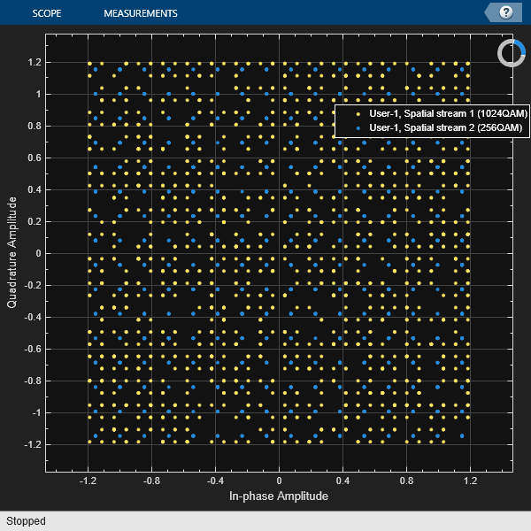
The figure shows the data symbols constellation for user 1 using UEQM.
userNumber = 1;
plotConstellation(tx,cfgOFDMA,userNumber);
Large MRU Packet Generation
A UHR MU transmission with a channel bandwidth greater than 20 MHz uses two content channels to signal the common and user configuration information. These content channels are duplicated over each 40 MHz subchannel within an 80 MHz segment. When an OFDMA system contains an RU with size greater than 242, the users assigned to the RU can be signaled on either of the two UHR SIG content channels as defined in section 38.3.15.9 of [1].
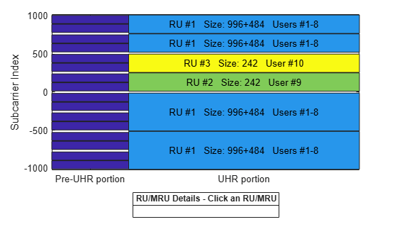
As an example, consider this 160 MHz configuration, which serves ten users with three RUs including a 996-[ ]-484 MRU:
A large 996+484-tone MRU (RU 1) with eight users (user 1**–**8)
A 242-tone RU (RU 2) with one user (user 9)
A 242-tone RU (RU 3) with one user (user 10)
Configure a 160 MHz OFDMA transmission with eight allocation indices, one for each 20 MHz subchannel. To configure the example scenario, use these allocation indices.
[X1 X2 X3 X4 64 64 X5 X6]
X1toX6configure the 996+484-tone MRU, with users 1**–**8.Allocation index 64 configures a 242-tone RU with one user.
The choice of X1 to X6 configures the appropriate number of users through an allocation index in the 20 MHz subchannel and determines which UHR-SIG content channel signals the users on the 996+484-tone RU. A 996+484-tone RU spans six 20 MHz subchannels. The two 242-tone RUs each indicated by allocation index 64 span two 20 MHz subchannels within MRU 996-[ ]-484. The 996+484-tone MRU requires six allocation indices indicated by X1 to X6. The ten users can be signaled on two UHR-SIG content channels in different combinations. Table 1 shows seven of the numerous possible combinations.
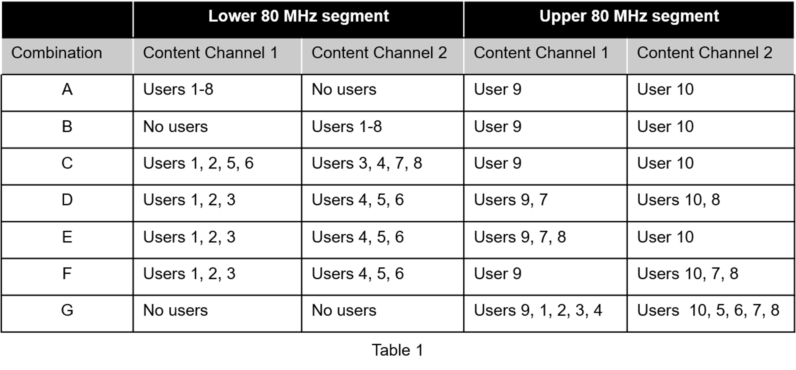
An allocation index in the range 144–151 specifies 1–8 users on a 996+484-tone MRU. To signal no users on a content channel, use allocation index 29 or 30 when the 20 MHz subchannel corresponding to the index overlaps with a 448-tone or 996-tone RU, respectively. Therefore, the combinations in Table 1 require eight allocation indices as shown in Table 2. Other than allocation index 64, the remaining six allocation indices in each row of Table 2 are X1 to X6. Table 2 shows the number of users on each content channel in the two 80 MHz segments for various combinations of RU allocation index.
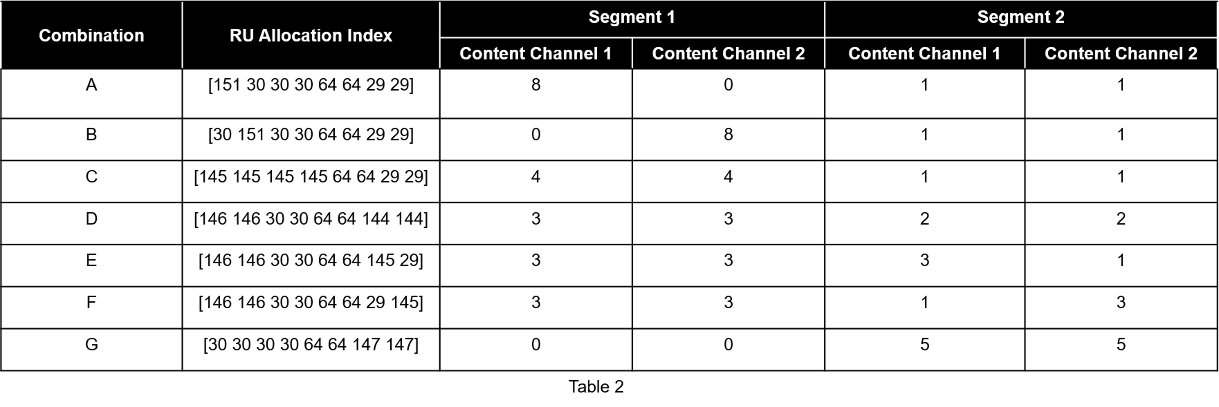
Configure the transmission parameters for a UHR MU packet format for the OFDMA configuration with a UHR MU configuration object. Configure Combination C from Table 2 by using the allocation indices [145 145 145 145 64 64 29 29].
cfgLMRU = uhrMUConfig([145 145 145 145 64 64 29 29]); % 1 MRU (996+484) with 8 users and two 242-tone RUs with one user each
cfgLMRU.NumTransmitAntennas = 8;
Set transmission parameters for the users.
userSTS = [1 1 1 1 1 1 1 1 8 8]; % Number of space time streams per user
allocInfo = ruInfo(cfgLMRU);     % Get details of the RU/MRU in the configuration
for u=1:allocInfo.NumUsers
    cfgLMRU.User{u}.NumSpaceTimeStreams = userSTS(u);
    cfgLMRU.User{u}.MCS = 12;
    cfgLMRU.User{u}.APEPLength = randi([100 500],1,1);
end
Create a packet with a repeated bit sequence as the PSDU.
tx = uhrWaveformGenerator([1 0 1 0],cfgLMRU);
Visualize the RU allocation.
showAllocation(cfgLMRU)
Preamble Puncturing
Create a configuration for an OFDMA 160 MHz transmission with punctured subchannels. Use the 20 MHz subchannel allocation index 26 to puncture a 20 MHz subchannel. Puncture the second 20 MHz subchannel in the lower 80 MHz segment. Puncture the second and third 20 MHz subchannels in the upper 80 MHz segment.
cfgPuncture = uhrMUConfig([64 26 64 64 64 26 26 64]);
for u=1:numel(cfgPuncture.User)
    cfgPuncture.User{u}.APEPLength = 1000;
end
Generate an oversampled waveform using a larger IFFT size than required for the nominal baseband rate.
osf = 1.5;
txPuncture = uhrWaveformGenerator([1 0 1 0],cfgPuncture,OversamplingFactor=osf);
View the punctured 20 MHz subchannels in the generated waveform by using the spectrum analyzer.
sa = plotSpectrumAndSpectrogram(txPuncture,cfgPuncture,osf,"160 MHz UHR MU Transmission with Punctured 20 MHz Channels");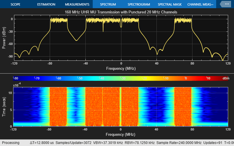
Unassigned RUs
The draft standard allows for RUs to be unassigned (no data transmitted) without the preamble portion of the corresponding 20 MHz being punctured. The standard specifies two methods for creating unassigned RUs: using an unassigned 242-tone allocation index or signaling a user with STA-ID 2046.
Unassigned 242-tone Allocation Index
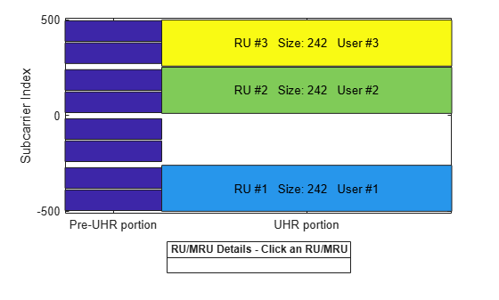
Configure an 80 MHz transmission with no data transmission in a 20 MHz subchannel without preamble puncturing by using allocation index 27.
cfgUnassigned = uhrMUConfig([64 27 64 64]);
for u=1:numel(cfgUnassigned.User)
    cfgUnassigned.User{u}.APEPLength = 1000;
end
Visualize the RU allocation, which shows that the preamble is not punctured.
showAllocation(cfgUnassigned);
Generate an oversampled waveform and view the spectrogram. The preamble is visible in all 20 MHz subchannels at the start of the waveform.
osf = 1.5;
tx = uhrWaveformGenerator([1 0 0 1],cfgUnassigned,OversamplingFactor=osf);
sa = plotSpectrumAndSpectrogram(tx,cfgUnassigned,osf,"80 MHz UHR MU Transmission with Unassigned 20 MHz Channel");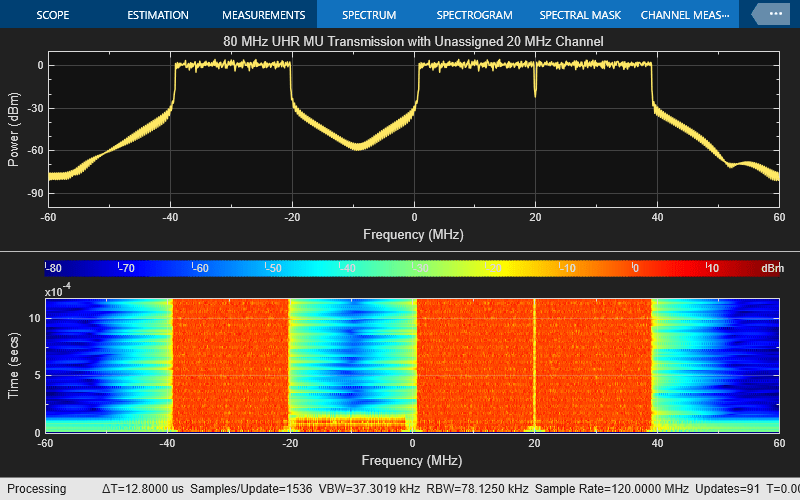
Signal User with STA-ID 2046
The draft standard states an RU is unassigned (no data transmitted) if the STA-ID of the UHR-SIG User field is 2046.
Create a 20 MHz OFDMA configuration with four RUs with a user in each RU using allocation index 52.
cfgUnassigned = uhrMUConfig(52);
Visualize the RU allocation.
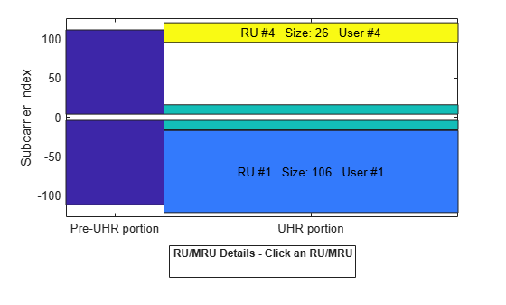
showAllocation(cfgUnassigned)
Set the STAID property of the third user to 2046 so that the 52+26-tone MRU is unassigned.
cfgUnassigned.User{3}.STAID = 2046; % No data transmitted to 3rd user on MRU 52+26Visualize the RU allocation, which shows that the third RU is now unassigned but the preamble is not punctured.
showAllocation(cfgUnassigned)
View details of the RUs in the configuration by using the ruInfo object function. This allocation shows three active RUs (see allocInfo.RUAssigned) because RU 3 is unassigned due to the third user having STAID 2046.
allocInfo = ruInfo(cfgUnassigned);
disp("Allocation info:")
Allocation info:
disp(allocInfo)
                    NumUsers: 4
                      NumRUs: 4
                   RUIndices: {[1]  [5]  [3 8]  [9]}
                     RUSizes: {[106]  [26]  [52 26]  [26]}
               NumUsersPerRU: [1 1 1 1]
    NumSpaceTimeStreamsPerRU: [1 1 1 1]
       PowerBoostFactorPerRU: [1 1 1 1]
                   RUNumbers: [1 2 3 4]
                  RUAssigned: [1 1 0 1]
UHR TB Packet Format
Each STA transmits a TB packet simultaneously when triggered by the access point (AP). An AP controls the TB transmission and provides the parameters to all STAs participating in the TB transmission through a trigger frame. The UHR TB format allows for:
OFDMA or MU-MIMO transmission in the uplink without DRU
OFDMA transmission in the uplink with DRU
UHR TB packets support transmission over both regular resource units (RRUs) and distributed resource units (DRUs). An RRU (another term for an RU) is a contiguous block of subcarriers. Each user is assigned one or more RUs for uplink transmissions. The DRU is a new feature introduced in Wi-Fi 8. Unlike RRUs, DRUs enable the grouping of noncontiguous subcarriers assigned to a single user for uplink transmission. The DRU enables you to overcome power spectral density (PSD) limitations and boosts transmit power by spreading a user’s subcarriers across a distribution bandwidth (DBW). A DBW is the portion of bandwidth within the full PPDU bandwidth where the DRU subcarriers are distributed noncontiguously for a single uplink user.
UHR TB transmission supports 26-, 52-, 106-, 242-, and 484-tone subcarriers, which are distributed across 20, 40, and 80 MHz distribution bandwidths. For more details on DRU transmission, see section 38.3.4 of [1].
TB Transmission
Single-STA TB Waveform
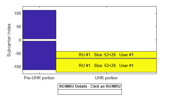
Configure the parameters for a TB transmission on a 52+26-tone MRU in a 20 MHz bandwidth. Use a uhrTBConfig object to configure a TB transmission and set the user properties as shown in this example:
cfgTB = uhrTBConfig;
cfgTB.ChannelBandwidth = "CBW20";
cfgTB.RUSize = [52 26];
cfgTB.RUIndex = [1 3];
Visualize the RU allocation with the showAllocation object function.
showAllocation(cfgTB);
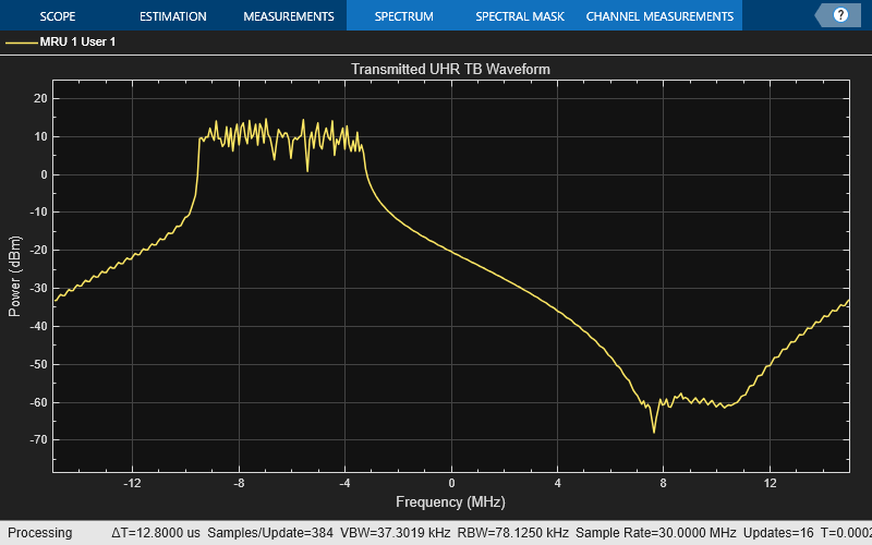
Transmit a packet containing random data for the user with uhrWaveformGenerator and visualize the frequency spectrum.
osf = 1.5; % Over sampling factor
txPSDU = randi([0 1],psduLength(cfgTB)*8,1);
txTrig = uhrWaveformGenerator(txPSDU,cfgTB,OversamplingFactor=osf);
% The spectrum of the transmitted waveform
spectrumScope = plotSpectrum(cfgTB,osf,{"MRU 1 User 1"},"Transmitted UHR TB Waveform");
spectrumScope(txTrig);
Multi-STA TB Waveform
This example allows you to generate a waveform for multiple STAs participating in a TB response to an AP. The example uses the allocation index to parameterize the RUs for four users in an OFDMA/MU-MIMO system.
The 80 MHz allocation range 104 to 111 corresponds to a large MRU in an OFDMA/MU-MIMO configuration. As an example, the allocation 104 and 50 corresponds to three RU/MRUs, where:
A 242-[]-484-tone large size MRU (RU 1) has two users (user 1**–**2)
A 106-tone RU (RU 2) has one user (user 3)
A 106+26-tone small size MRU (RU 3) has one user (user 4)
Use a uhrTBSystemConfig object to obtain the allocation information for multiple users in an uplink transmission.
% Generate an OFDMA/MU-MIMO allocation
cfgSys = uhrTBSystemConfig([104 50 104 29]);
In a TB transmission, some parameters are the same for all uplink users, while some can differ. The User property of cfgSys contains a cell array of user configurations. Each element of the cell array is an object that sets the parameters of an individual user. In this example, all users have the same transmission parameters.
% These parameters are the same for all users in the MU-MIMO system
cfgSys.UHRLTFType = 4;      % UHR-LTF compression mode
cfgSys.GuardInterval = 3.2; % Guard interval type
numRx = 8;                  % Number of receive(AP) antennas

% The individual parameters for each user are specified below
numUsers = numel(cfgSys.User); % Number of uplink users
for userIdx = 1:numUsers
    cfgSys.User{userIdx}.NumTransmitAntennas = 1;
    cfgSys.User{userIdx}.NumSpaceTimeStreams = 1;
    cfgSys.User{userIdx}.SpatialMapping = "Direct";
    cfgSys.User{userIdx}.MCS = 7;
    cfgSys.User{userIdx}.APEPLength = 1e3;
    cfgSys.User{userIdx}.ChannelCoding = "LDPC";
end
allocInfo = ruInfo(cfgSys);
When multiple users transmit in the same RU/MRU, in an MU-MIMO configuration, each user must transmit on different space-time stream indices.
The userConfig object function configures the transmission for all users. This example creates a cell array of four UHR TB objects that describes the transmission of four users.
cfgTBUsers = userConfig(cfgSys);
Each user transmits a packet that contains random data with uhrWaveformGenerator. The example stores the waveform each user transmits for analysis.
osf = 1.5; % Over sampling factor
trigInd = uhrFieldIndices(cfgTBUsers{1},OversamplingFactor=osf); % Get the indices of each field
txTrigStore = zeros(trigInd.UHRData(2),numUsers);
for userIdx = 1:numUsers
    % Generate waveform for a user
    cfgTB = cfgTBUsers{userIdx};
    txPSDU = randi([0 1],psduLength(cfgTB)*8,1);
    txTrig = uhrWaveformGenerator(txPSDU,cfgTB,OversamplingFactor=osf);

    % Store the transmitted STA waveform for analysis
    txTrigStore(:,userIdx) = txTrig;
end
The spectrum of the transmitted oversampled waveform from each STA shows the different portions of the spectrum used, and the overlap in the MU-MIMO RU.
spectrumScope = plotSpectrum(cfgTBUsers{1},osf,{"MRU 1 User 1","MRU 1 User 2","RU 2","MRU 3"},"Transmitted UHR TB Waveform per User");
spectrumScope(txTrigStore);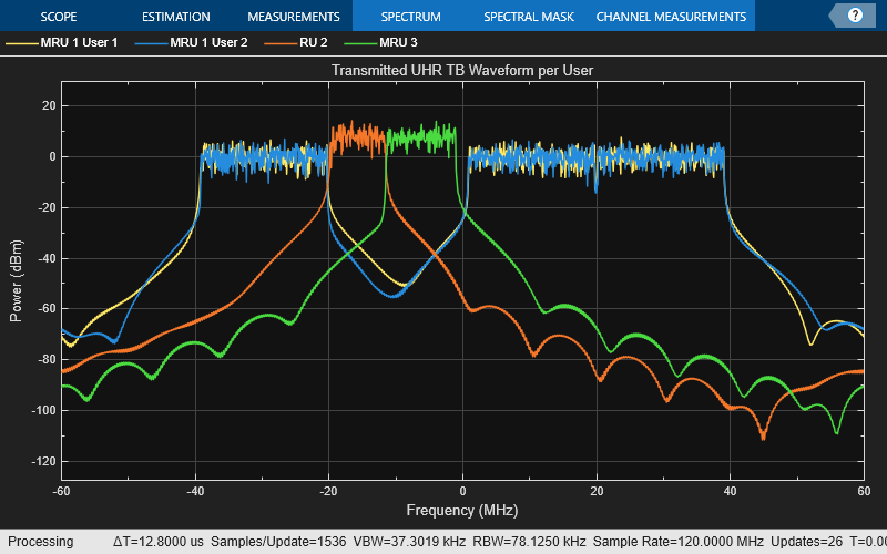
TB Transmission with DRU
Single-STA TB Waveform
This example allows you to create an OFDMA transmission in the uplink with DRU. The 52-tone noncontiguous subcarriers are assigned to a single user in an uplink transmission in a 80 MHz DBW.
% Generate a UHR TB waveform for user on a DRU
cfgTB = uhrTBConfig;
cfgTB.ChannelBandwidth = "CBW80";
cfgTB.RUSize = 52;
cfgTB.RUIndex = 1;
cfgTB.DRU = true; % Enable DRU
cfgTB.DistributionBandwidth = "DBW80"; % DBW
Visualize the 52-tone noncontiguous subcarriers.
showAllocation(cfgTB);

Transmit a packet containing random data for the user with uhrWaveformGenerator.
% Transmit a packet containing random data for the user
osf = 1.5;
txPSDU = randi([0 1],psduLength(cfgTB)*8,1);
txUserDRU = uhrWaveformGenerator(txPSDU,cfgTB,OversamplingFactor=osf);
Set the DRU property of cfgTB to false. This generates a TB transmission on an RRU (52-tone contiguous subcarrier).
cfgTB.DRU = false; % Disable transmission on a DRUTransmit a packet containing random data for the user with uhrWaveformGenerator and visualize the frequency spectrum for a TB transmission with and without DRU.
osf = 1.5;
txPSDU = randi([0 1],psduLength(cfgTB)*8,1);
txUser = uhrWaveformGenerator(txPSDU,cfgTB,OversamplingFactor=osf);

spectrumScope = plotSpectrum(cfgTB,osf,{"52-tone User 1 (DRU)","52-tone User 1 (RRU)"},"Transmitted UHR TB Waveform");
spectrumScope([txUserDRU txUser]);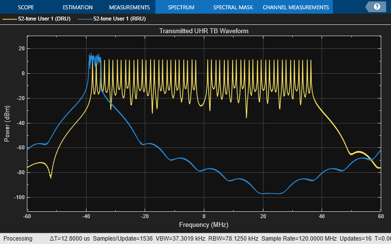
Multi-STA TB Waveform
This example allows you to create waveform configurations for multiple STAs participating in a TB response to an AP. The example uses the allocation index to parameterize the RUs for an OFDMA system.
This example creates an OFDMA configuration for an 80 MHz UHR TB packet with sixteen 52-tone STAs on DRUs. Use the uhrTBSystemConfig object to facilitate creating multiple uplink stations. The DRUIndication input indicates whether a DRU or an RRU transmission is solicited in each 80 MHz frequency subblock. The DistributionBandwidth input is a cell array for each 80 MHz frequency subblock indicating the distributed bandwidth as one of 20, 40, or 80 MHz. See the Wi-Fi 8 Packet Error Rate Simulation for Uplink Trigger-Based Format with DRUs example on setting DRUIndication and DistributionBandwidth in an uplink OFDMA configuration.
cfgSys = uhrTBSystemConfig([24 24 24 24],DRUIndication=true,DistributionBandwidth={80});The User property of cfgSys contains a cell array of user configurations. Each element of the cell array is an object that sets the parameters of an individual user. In this example, all users have the same transmission parameters.
% These parameters are the same for all users in the OFDMA system
cfgSys.UHRLTFType = 4;      % UHR-LTF compression mode
cfgSys.GuardInterval = 3.2; % Guard interval type
numRx = 8;                  % Number of receive (AP) antennas

% The individual parameters for each user are specified below
numUsers = numel(cfgSys.User); % Number of uplink users
for userIdx = 1:numUsers
    cfgSys.User{userIdx}.NumTransmitAntennas = 1;
    cfgSys.User{userIdx}.NumSpaceTimeStreams = 1;
    cfgSys.User{userIdx}.SpatialMapping = "Direct";
    cfgSys.User{userIdx}.MCS = 5;
    cfgSys.User{userIdx}.APEPLength = 1e3;
    cfgSys.User{userIdx}.ChannelCoding = "LDPC";
end
allocInfo = ruInfo(cfgSys);
The method userConfig of uhrTBSystemConfig object configures the transmission for all users in the given OFDMA system. This example creates a cell array of sixteen uhrTBConfig objects that describes the transmission of sixteen users on DRU.
cfgTBUsers = userConfig(cfgSys);
The first user configuration shows the DRU and DistributionBandwidth property set to true and "DBW80", respectively.
disp(cfgTBUsers{1}) uhrTBConfig with properties:
ChannelBandwidth: 'CBW80'
RUSize: 52
RUIndex: 1
DRU: 1
DistributionBandwidth: 'DBW80'
PreUHRPowerScalingFactor: 1
NumTransmitAntennas: 1
NumSpaceTimeStreams: 1
StartingSpaceTimeStream: 1
SpatialMapping: direct
MCS: 5
ChannelCoding: ldpc
PreFECPaddingFactor: 4
LDPCExtraSymbol: 1
PEDisambiguity: 0
LSIGLength: 526
GuardInterval: 3.2000
UHRLTFType: 4
NumUHRLTFSymbols: 1
BSSColor: 0
SpatialReuse1: 15
SpatialReuse2: 15
TXOPDuration: []
DisregardBitsUSIG1: [6×1 int8]
ValidateBitUSIG2: 1
DisregardBitsUSIG2: [5×1 int8]
PostFECPaddingSource: mt19937arwithseed
PostFECPaddingSeed: 1
Visualize the RU allocation for the first 52-tone DRU user.
showAllocation(cfgTBUsers{1})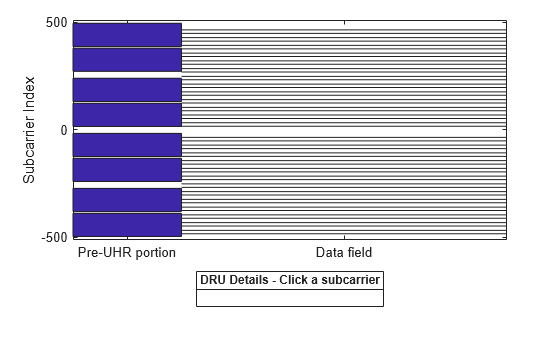
A packet containing random data is now transmitted by each user on a DRU with uhrWaveformGenerator. The waveform transmitted by each user is stored for analysis.
osf = 1.5; % Over sampling factor
trigInd = uhrFieldIndices(cfgTBUsers{1},OversamplingFactor=osf); % Get the indices of each field
txTrigStore = zeros(trigInd.UHRData(2),numUsers);
for userIdx = 1:numUsers
    % Generate waveform for a user
    cfgTB = cfgTBUsers{userIdx};
    txPSDU = randi([0 1],psduLength(cfgTB)*8,1);
    txTrig = uhrWaveformGenerator(txPSDU,cfgTB,OversamplingFactor=osf);

    % Store the transmitted STA waveform for analysis
    txTrigStore(:,userIdx) = sum(txTrig,2);
end
Visualize the frequency spectrum of the first and the last user on a 52-DRU.
spectrumScope = plotSpectrum(cfgTBUsers{1},osf,{"52-tone User 1 (DRU)","52-tone User 16 (DRU)"},"Transmitted UHR TB Waveform");
spectrumScope([txTrigStore(:,1) txTrigStore(:,numUsers)]);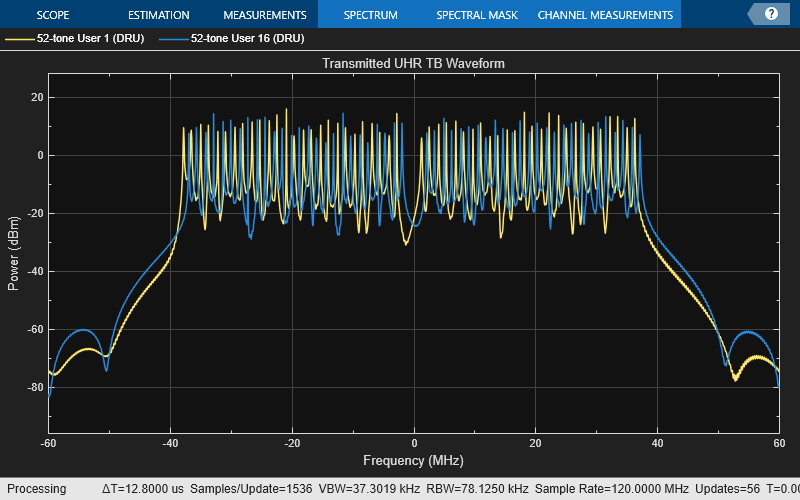
ELR Packet Format
The ELR packet format is a new feature introduced in Wi-Fi 8, designed to enable long-range communication for stations located farther from the access point. ELR operates exclusively at 20 MHz channel bandwidths. It supports both downlink and uplink communication in the 2.4 GHz band but is limited to uplink communication in the 5 GHz and 6 GHz bands. The ELR packet format accommodates BPSK and QPSK modulation on a single spatial stream. The PPDU supports either BCC or LDPC coding, with codeword block lengths of up to 1944 bits, guard intervals of 1.6 μs, and the 2xUHR-LTF UHR-LTF type
The ELR packet enhances the reliability of long-range transmission by assigning 3 dB higher power to the L-STF, L-LTF, UHR-LTF, and UHR-STF fields compared to the data field. Additionally, the ELR-SIG and ELR-Data transmission is replicated across four 52-tone regular RUs within the 20 MHz channel bandwidth (see section 38.3.16.9 [1]). This repetition increases reliability at the expense of the data rate.
This example enables you to create waveform configurations for an ELR packet. The example transmits a packet containing random data for the user with uhrWaveformGenerator.
cfgELR = uhrELRConfig;
txPSDU = randi([0 1],psduLength(cfgELR)*8,1);
txELR = uhrWaveformGenerator(txPSDU,cfgELR,OversamplingFactor=osf);
Visualize the RU allocation.
showAllocation(cfgELR)
Local functions
function spectrumScope = plotSpectrumAndSpectrogram(tx,cfg,osf,titleStr)
%plotSpectrumAndSpectrogram Plot the spectrum and spectrogram for a given waveform and configuration

    fs = wlanSampleRate(cfg.ChannelBandwidth,OversamplingFactor=osf); % Get baseband sample rate
    ofdmInfo = uhrOFDMInfo("UHR-Data",cfg,1,OversamplingFactor=osf);
    fftsize = ofdmInfo.FFTLength; % Use the data field fft size
    rbw = fs/fftsize; % Resolution bandwidth
    spectrumScope = spectrumAnalyzer(SampleRate=fs,...
    RBWSource="property",RBW=rbw,...
    AveragingMethod="exponential",ForgettingFactor=0.25,...
    ReducePlotRate=false,YLimits=[-100,10],...
    Title=titleStr);
    spectrumScope.ViewType = "spectrum-and-spectrogram";
    spectrumScope.TimeSpanSource = "property";
    spectrumScope.TimeSpan = length(tx)/fs;
    spectrumScope(tx)
end

function plotConstellation(tx,cfg,userNumber)
%plotConstellation Plot constellation for all spatial streams

    fs = wlanSampleRate(cfg.ChannelBandwidth); % Get baseband sample rate
    ofdmInfo = uhrOFDMInfo("UHR-Data",cfg,userNumber);
    ind = uhrFieldIndices(cfg);
    rxUHRLTF = tx(ind.UHRLTF(1):ind.UHRLTF(2),:);
    rxUHRData = tx(ind.UHRData(1):ind.UHRData(2),:);
    demodUHRLTFRU = uhrDemodulate(rxUHRLTF,"UHR-LTF",cfg,userNumber);
    demodHUHRDataRU = uhrDemodulate(rxUHRData,"UHR-Data",cfg,userNumber);
    chanEst = uhrLTFChannelEstimate(demodUHRLTFRU,cfg,userNumber);
    eqSym = uhrEqualize(demodHUHRDataRU(ofdmInfo.DataIndices,:,:),chanEst(ofdmInfo.DataIndices,:,:),0,cfg,"UHR-Data",userNumber);

    % Create a constellation diagram to plot equalized symbols
    % Scale and position plots on the screen

    ConstellationDiagram = comm.ConstellationDiagram;
    ConstellationDiagram.ShowReferenceConstellation = false;
    ConstellationDiagram.ShowGrid = true;
    ConstellationDiagram.Name = "Equalized data symbols";
    ConstellationDiagram.ShowLegend = 1;

    [Nsd,Nsym,Nss] = size(eqSym);
    eqDataSymPerSS = reshape(eqSym,Nsd*Nsym,Nss);

    str = cell(Nss,1);
    for iss=1:Nss
        str{iss} = sprintf("User-%d, Spatial stream %d (%s)",userNumber,iss,cfg.User{userNumber}.Modulation(iss));
    end

    ConstellationDiagram(eqDataSymPerSS);
    show(ConstellationDiagram);

    if nargin>3
        ConstellationDiagram.Name = sprintf("Equalized data symbols, user #%d/%d",userIdx,numUsers);
    else
        ConstellationDiagram.Name = sprintf("Equalized data symbols");
    end
    ConstellationDiagram.ChannelNames = str;
    release(ConstellationDiagram);
end
function spectrumScope = plotSpectrum(cfg,osf,channelName,titleStr)
%plotSpectrum Plot spectrum

    fs = wlanSampleRate(cfg.ChannelBandwidth,OversamplingFactor=osf);
    ofdmInfo = uhrOFDMInfo("UHR-Data",cfg,OversamplingFactor=osf);
    rbw = fs/ofdmInfo.FFTLength; % Resolution bandwidth
    spectrumScope = spectrumAnalyzer(SampleRate=fs,...
                RBWSource="property",RBW=rbw,...
                AveragingMethod="exponential",ForgettingFactor=0.25,...
                ChannelNames=channelName,...
                ShowLegend=true,Title=titleStr);
end
RU Allocation Subfield
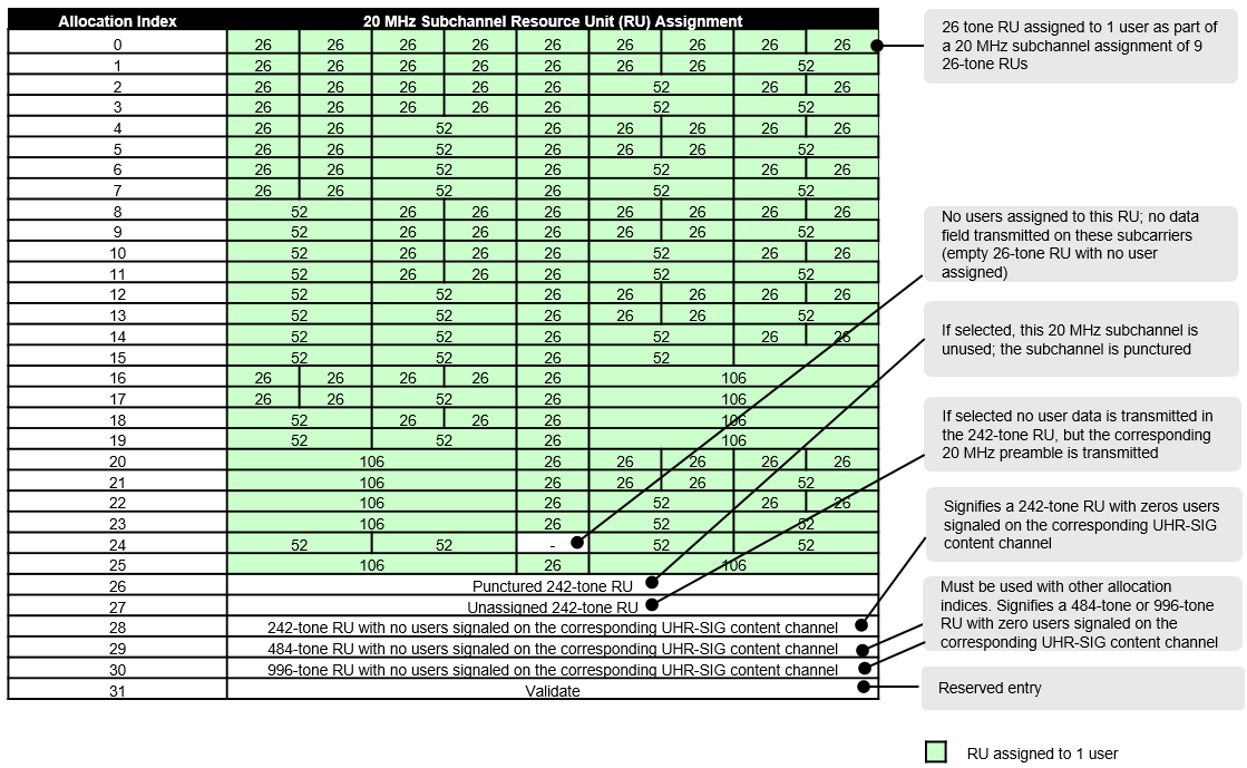
The RU allocation subfield table for allocations <= 20 MHz is shown below, with annotated descriptions. See Table 38-28 [1].
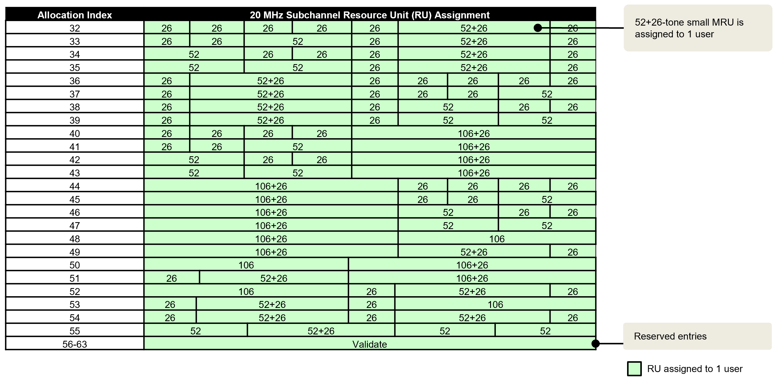
This table describes the RU allocation and UHR-SIG user signaling for allocations >= 20 MHz, with annotated descriptions. See Table 38-28 [1].
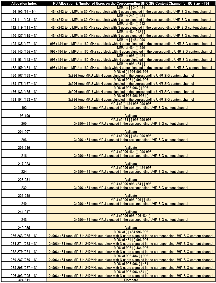
This table describes the RU allocation and UHR-SIG user signaling for 242-, 484-, 996-, and 2x996-tone RUs. See Table 38-28 [1].
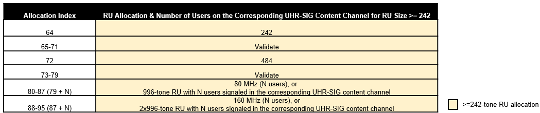
This table describes the MRU allocation and UHR-SIG user signaling for allocation >=80 MHz. See Table 38-28 [1].
Punctured Channel Information
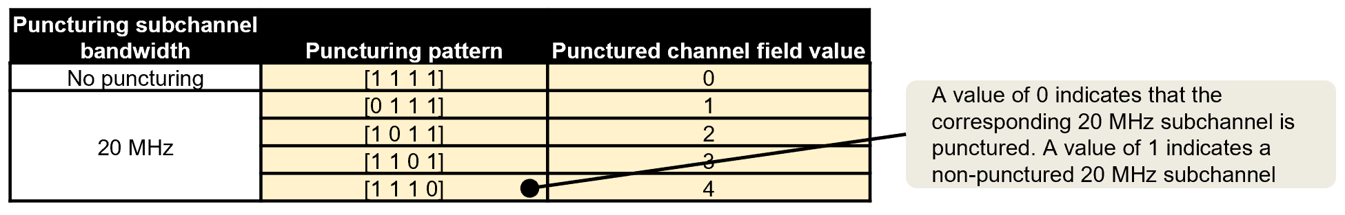
This table describes the non-OFDMA punctured channel indication for a 80 MHz PPDU, with annotated descriptions. See Table 36-30 [2].
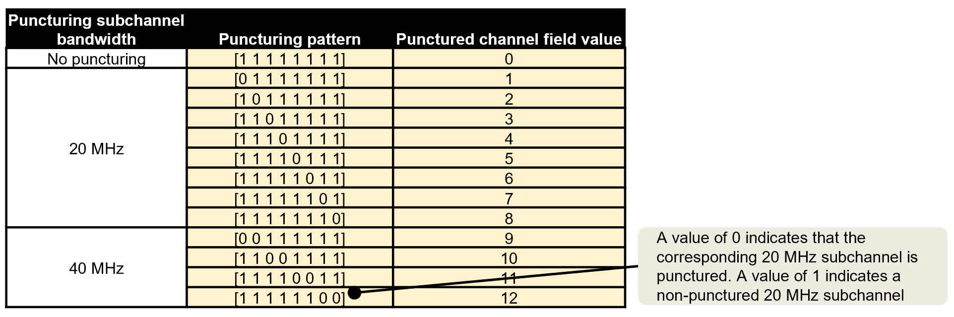
This table describes the non-OFDMA punctured channel indication for a 160 MHz PPDU, with annotated descriptions. See Table 36-30 [2].
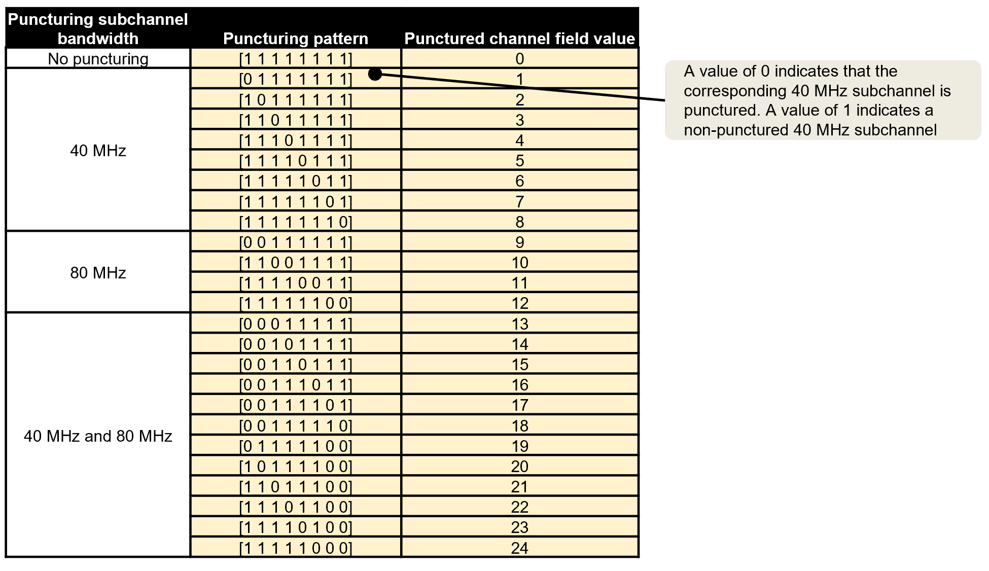
This table describes the non-OFDMA punctured channel indication for a 320 MHz PPDU. See Table 36-30 [2].
References
[1] IEEE P802.11bn™/D1.0. Draft Standard for Information technology - Telecommunications and Information Exchange between Systems Local and Metropolitan Area Networks--Specific Requirements - Part 11: Wireless LAN Medium Access Control (MAC) and Physical Layer (PHY) Specifications Amendment 6: Enhancements for Ultra High Reliability (UHR).
[2] IEEE Std P802.11be-2024. IEEE Standard for Information technology - Telecommunications and Information Exchange between Systems - Local and Metropolitan Area Networks--Specific Requirements - Part 11: Wireless LAN Medium Access Control (MAC) and Physical Layer (PHY) Specifications Amendment 2: Enhancements for Extremely High Throughput (EHT).