Wi-Fi 8 Downlink Packet Error Rate Simulation Using Unequal Modulation
This example shows how to measure the packet error rate (PER) of a beamformed IEEE® 802.11bn™ ultra high reliability (UHR) single-user MIMO (SU-MIMO) link that uses unequal modulation (UEQM).
Introduction
Unequal modulation (UEQM) is a new feature introduced in Wi-Fi® 8, also referred to as 802.11bn UHR [1]. In a PPDU that uses UEQM, the uncoded bits sent across all spatial streams for a given user in the data field of the PPDU are jointly encoded. The resulting coded bits are then distributed among the spatial streams, with at least one stream using a different modulation order than the first spatial stream. Since higher modulation orders perform better at higher signal-to-noise ratios (SNRs) and beamforming causes different spatial streams to have different SNRs, UEQM is particularly well suited for use in beamforming scenarios [2]. The diagram below illustrates the default setup for simulating beamforming together with UEQM in this example.
Waveform Configuration
This example evaluates the PER of a beamformed Wi-Fi 8 SU-MIMO link that uses UEQM. To sound all subcarriers and estimate the channel without interpolation for this transmission configuration, use the 4x UHR-LTF compression mode. This example does not model subcarrier beamforming smoothing. This example also uses a doubled LDPC code length of 3888 to enhance the reliability. Additionally, you can configure this example to disable beamforming or UEQM.
useBeamforming =true; NumTxAnts = 4; % Number of transmit antennas NumSTS = 2; % Number of space-time streams NumRxAnts = 2; % Number of receive antennas if useBeamforming spatialMapping = 'Custom'; % Custom for beamforming Ng = 16; % Subcarrier grouping for beamforming. Ng must be 1 (no grouping), 4, or 16. else spatialMapping = 'Fourier'; %#ok<UNRCH> % Fourier mapping for non-beamforming end chanBW = 'CBW20'; % Channel bandwidth cfgUHRBase = uhrMUConfig(chanBW); cfgUHRBase.NumTransmitAntennas = NumTxAnts; % Number of transmit antennas cfgUHRBase.GuardInterval = 3.2; % Guard interval duration cfgUHRBase.UHRLTFType = 4; % UHR-LTF compression mode cfgUHRBase.User{1}.NumSpaceTimeStreams = NumSTS; % Number of space-time streams cfgUHRBase.User{1}.APEPLength = 1e4; % Payload length in bytes cfgUHRBase.User{1}.ChannelCoding = 'ldpc2x'; % 2xLDPC Channel coding cfgUHRBase.RU{1}.SpatialMapping = spatialMapping; % Spatial mapping
To enable UEQM, you must set different modulation and coding scheme (MCS) values for each spatial stream and ensure that the coding rate is the same for all streams. For the example below, the first spatial stream uses 4096-QAM (MCS 13), while the second uses 1024-QAM (MCS 11). Both MCS 13 and MCS 11 have a coding rate of 5/6. The standard [1] specifies certain allowed combinations of modulation schemes, referred to as UEQMPattern. You can check the UEQM relevant information using the read-only properties of the uhrUser object. For equal modulation (EQM), since the same MCS applies to all spatial streams, specify the MCS as a scalar.
useUEQM =true; if useUEQM % 1st SS - 4096 QAM % 2nd SS - 1024 QAM mcs = [13 11]; else mcs = 13; %#ok<UNRCH> end cfgUHRBase.User{1}.MCS = mcs; % Modulation and coding scheme disp(cfgUHRBase.User{1})
  uhrUser with properties:

              APEPLength: 10000
                     MCS: [13 11]
     NumSpaceTimeStreams: 2
           ChannelCoding: ldpc2x
                   STAID: 0
    NominalPacketPadding: 0
    PostFECPaddingSource: mt19937arwithseed
      PostFECPaddingSeed: 1

   Read-only properties:
                RUNumber: 1
                    UEQM: 1
              Modulation: ["4096QAM"    "1024QAM"]
              CodingRate: ["5/6"    "5/6"]
             UEQMPattern: 0
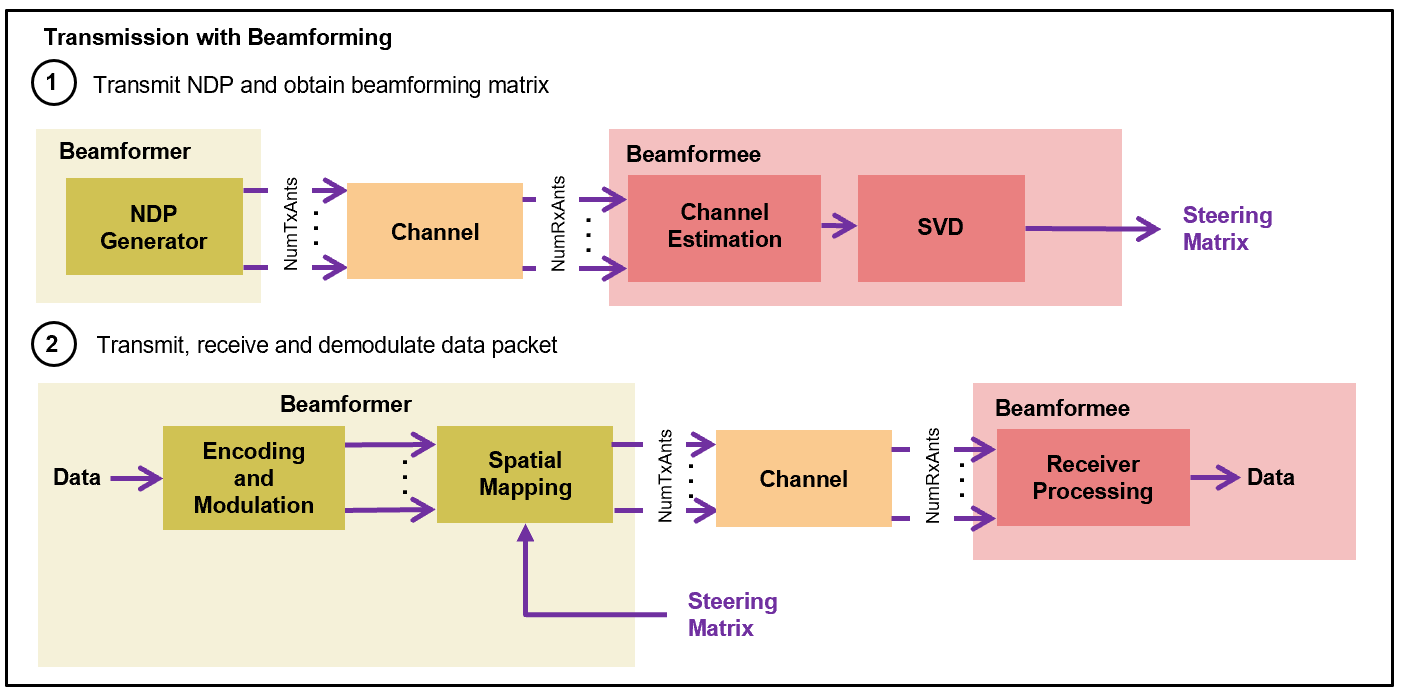
Beamforming Configuration
Transmit beamforming focuses energy toward a receiver to improve the SNR of a link. In this scheme, the transmitter is called a beamformer and the receiver is called a beamformee. The beamformer uses a steering matrix to direct the energy to the beamformee. The beamformer calculates the steering matrix using channel state information (CSI) obtained through channel measurements. These measurements are obtained by sounding the channel between beamformer and beamformee. To sound the channel, the beamformer sends a null data packet (NDP) to the beamformee. The beamformee measures the channel information during sounding to calculate a feedback matrix [3]. The process of forming the steering matrix is shown in the 802.11ac Transmit Beamforming example. This example uses a subcarrier grouping of 16 and assumes no CSI feedback compression. For more information on subcarrier grouping and CSI feedback compression, see the 802.11ax Compressed Beamforming Packet Error Rate Simulation example.
Configure the NDP transmission to have a data length of zero. Since the NDP is used to obtain the channel state information, set the number of space-time streams equal to the number of transmit antennas and directly map each space-time stream to a transmit antenna.
if useBeamforming
    cfgNDP = cfgUHRBase;
    cfgNDP.User{1}.APEPLength = 0;                     % NDP has no data
    cfgNDP.User{1}.NumSpaceTimeStreams = NumTxAnts;    % For feedback matrix calculation
    cfgNDP.User{1}.MCS = 0;                            % Set MCS to 0 to skip UEQM validation
    cfgNDP.RU{1}.SpatialMapping = 'Direct';            % Each TxAnt carries an STS

    if Ng>1
        % Subcarrier grouping
        indicesGrouping = helperCompressedBeamformingSubcarrierIndices(cfgNDP,Ng);
    end

    % Transmit null data packet and add trailing zeros to allow for channel delay
    ndpTxWaveform = [uhrWaveformGenerator([],cfgNDP); zeros(50,cfgNDP.NumTransmitAntennas)];

    indSound = uhrFieldIndices(cfgNDP);
end
Channel Configuration
This example uses a TGax NLOS indoor channel model with delay profile Model-B. For more information, see wlanTGaxChannel.
% Create and configure the TGax channel
tgaxChannel = wlanTGaxChannel;
tgaxChannel.DelayProfile = 'Model-B';
tgaxChannel.NumTransmitAntennas = NumTxAnts;
tgaxChannel.NumReceiveAntennas = NumRxAnts;
tgaxChannel.TransmitReceiveDistance = 5; % Distance in meters for NLOS
tgaxChannel.ChannelBandwidth = chanBW;
tgaxChannel.LargeScaleFadingEffect = 'None';
tgaxChannel.NormalizeChannelOutputs = false;
fs = wlanSampleRate(chanBW);
tgaxChannel.SampleRate = fs;
Simulation Parameters
Set the SNRs to simulate in dB.
if useBeamforming
    snr = 31:3:43;
else
    snr = 39:6:63; %#ok<UNRCH>
end

if useUEQM
    snr = snr-3;     % Shift SNR values for UEQM scenarios
end
Limit the number of packets tested at each SNR point to maxNumErrors or maxNumPackets, where:
maxNumErrorsis the maximum number of packet errors simulated at each SNR point. When the number of packet errors reaches this limit, the simulation at this SNR point is complete.maxNumPacketsis the maximum number of packets simulated at each SNR point and limits the length of the simulation if the packet error limit is not reached.
The numbers in this example result in a very short simulation. For statistically meaningful results, increase these numbers.
maxNumErrors = 10;   % The maximum number of packet errors at an SNR point
maxNumPackets = 100; % The maximum number of packets at an SNR point
SNR Point Processing
For each SNR point, test packets and calculate the PER. For each packet, perform these steps:
Obtain Steering Matrix to create Feedback Matrix
Transmit an NDP waveform through an indoor TGax channel model. Model different channel realizations for different packets.
Add AWGN to the received waveform to create the desired average SNR per active subcarrier after OFDM demodulation.
Detect the packet at the beamformee.
Estimate and correct for coarse carrier frequency offset (CFO).
Establish fine timing synchronization.
Estimate and correct for fine CFO.
Extract the UHR-LTF from the synchronized received waveform. OFDM-demodulate the UHR-LTF and perform channel estimation.
Perform singular value decomposition on the estimated channel at grouped subcarriers and calculate the beamforming feedback matrix, V.
Transmit Data Packet using Recovered Steering Matrix
Use the V matrix calculated by the beamformee. Assume no beamforming feedback delay.
Create and encode a PSDU to create a single-packet waveform with the steering matrix set to the beamforming feedback matrix, V.
Pass the waveform through the same indoor TGax channel realization as the NDP transmission.
Add AWGN to the received waveform.
Decode Beamformed Data Transmission to Recover PSDU
As with NDP, perform synchronization and UHR channel estimation.
Extract the data field from the synchronized received waveform and OFDM-demodulate.
Perform common phase error pilot tracking to track any residual carrier frequency offset.
Estimate the noise power using the demodulated data field pilots and single-stream channel estimate at pilot subcarriers.
Equalize the phase-corrected OFDM symbols with the channel estimate.
Demodulate and decode the equalized symbols to recover the PSDU.
To parallelize processing of SNR points, you can use a parfor loop. To enable the use of parallel computing for increased speed comment out the for statement and uncomment the parfor statement below.
numSNR = numel(snr); % Number of SNR points
packetErrorRate = zeros(1,numSNR);

% Get occupied subcarrier indices and OFDM parameters
ofdmInfo = uhrOFDMInfo('UHR-Data',cfgUHRBase);

% Indices to extract fields from the PPDU
ind = uhrFieldIndices(cfgUHRBase);

% PSDU length in bytes
psduLengthInBytes = psduLength(cfgUHRBase);

%parfor isnr = 1:numSNR % Use 'parfor' to speed up the simulation
for isnr = 1:numSNR
    % Set random substream index per iteration to ensure that each
    % iteration uses a repeatable set of random numbers
    stream = RandStream('combRecursive','Seed',99);
    stream.Substream = isnr;
    RandStream.setGlobalStream(stream);

    % Convert the SNR per active subcarrier to total SNR to account for
    % noise energy in null subcarriers
    snrValue = convertSNR(snr(isnr),"snrsc","snr",...
        FFTLength=ofdmInfo.FFTLength,...
        NumActiveSubcarriers=ofdmInfo.NumTones);

    % Create an instance of the UHR configuration object per SNR point
    % simulated. This enables you to use parfor.
    cfgUHR = cfgUHRBase;

    % Loop to simulate multiple packets
    numPacketErrors = 0;
    numPkt = 1; % Index of packet transmitted
    while numPacketErrors<=maxNumErrors && numPkt<=maxNumPackets
        % Pass through a TGax indoor fading channel
        reset(tgaxChannel); % Reset channel for different realization

        if useBeamforming
            % NDP transmission
            rx = tgaxChannel(ndpTxWaveform);

            % Pass the waveform through AWGN channel
            rx = awgn(rx,snrValue);

            % Calculate the steering matrix at the beamformee
            V = helperUserBeamformingFeedback(rx,cfgNDP,indSound,Ng);

            if isempty(V)
                % User feedback failed, packet error
                numPacketErrors = numPacketErrors+1;
                numPkt = numPkt+1;
                continue; % Go to next loop iteration
            end

            % Subcarrier interpolation
            if Ng>1
                steeringMat = interpolateSteeringMatrix(V,ofdmInfo.NumTones,indicesGrouping);
            else
                steeringMat = V; % No grouping
            end

            cfgUHR.RU{1}.SpatialMappingMatrix = steeringMat;
        end

        % Data packet transmission
        txPSDU = randi([0 1],psduLengthInBytes*8,1); % Generate random PSDU
        tx = uhrWaveformGenerator(txPSDU,cfgUHR);

        % Add trailing zeros to allow for channel delay
        txPad = [tx; zeros(50,cfgUHR.NumTransmitAntennas)];

        % Pass through a fading indoor TGax channel
        rx = tgaxChannel(txPad);

        % Pass the waveform through AWGN channel
        rx = awgn(rx,snrValue);

        % Packet detect and determine coarse packet offset
        coarsePktOffset = wlanPacketDetect(rx,chanBW);
        if isempty(coarsePktOffset) % If empty no L-STF detected; packet error
            numPacketErrors = numPacketErrors+1;
            numPkt = numPkt+1;
            continue; % Go to next loop iteration
        end

        % Extract L-STF and perform coarse frequency offset correction
        lstf = rx(coarsePktOffset+(ind.LSTF(1):ind.LSTF(2)),:);
        coarseFreqOff = wlanCoarseCFOEstimate(lstf,chanBW);
        rx = frequencyOffset(rx,fs,-coarseFreqOff);

        % Extract the non-HT fields and determine fine packet offset
        nonhtfields = rx(coarsePktOffset+(ind.LSTF(1):ind.LSIG(2)),:);
        finePktOffset = wlanSymbolTimingEstimate(nonhtfields,chanBW);

        % Determine final packet offset
        pktOffset = coarsePktOffset+finePktOffset;

        % Register a packet error if packet detected outside
        % the range of expected delays from the channel modeling
        if pktOffset>50
            numPacketErrors = numPacketErrors+1;
            numPkt = numPkt+1;
            continue; % Go to next loop iteration
        end

        % Extract L-LTF and perform fine frequency offset correction
        rxLLTF = rx(pktOffset+(ind.LLTF(1):ind.LLTF(2)),:);
        fineFreqOff = wlanFineCFOEstimate(rxLLTF,chanBW);
        rx = frequencyOffset(rx,fs,-fineFreqOff);

        % UHR-LTF demodulation and channel estimation
        rxUHRLTF = rx(pktOffset+(ind.UHRLTF(1):ind.UHRLTF(2)),:);
        uhrltfDemod = uhrDemodulate(rxUHRLTF,'UHR-LTF',cfgUHR);
        [chanEst,pilotEst] = uhrLTFChannelEstimate(uhrltfDemod,cfgUHR);

        % Data demodulate
        rxData = rx(pktOffset+(ind.UHRData(1):ind.UHRData(2)),:);
        demodSym = uhrDemodulate(rxData,'UHR-Data',cfgUHR);

        % Pilot phase tracking
        % Average single-stream pilot estimates over symbols (2nd dimension)
        pilotEstTrack = mean(pilotEst,2);
        demodSym = uhrTrackPilotError(demodSym,pilotEstTrack,cfgUHR,'UHR-Data');

        % Estimate noise power in UHR fields
        nVarEst = uhrDataNoiseEstimate(demodSym(ofdmInfo.PilotIndices,:,:),pilotEstTrack,cfgUHR);

        % Extract data subcarriers from demodulated symbols and channel estimate
        demodDataSym = demodSym(ofdmInfo.DataIndices,:,:);
        chanEstData = chanEst(ofdmInfo.DataIndices,:,:);

        % Equalization
        [eqDataSym,csi] = uhrEqualize(demodDataSym,chanEstData,nVarEst,cfgUHR,'UHR-Data');

        % Recover data
        rxPSDU = uhrDataBitRecover(eqDataSym,nVarEst,csi,cfgUHR);

        % Determine if any bits are in error, i.e. a packet error
        packetError = ~isequal(txPSDU,rxPSDU);
        numPacketErrors = numPacketErrors+packetError;
        numPkt = numPkt+1;
    end

    % Calculate packet error rate (PER) at SNR point
    packetErrorRate(:,isnr) = numPacketErrors/(numPkt-1);
    disp(['MCS ' num2str(cfgUHR.User{1}.MCS) ','...
        ' SNR ' num2str(snr(isnr)) ' dB'...
        ' completed after ' num2str(numPkt-1) ' packets,'...
        ' PER:' num2str(packetErrorRate(:,isnr))]);
end
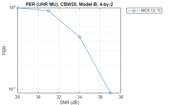
MCS 13  11, SNR 28 dB completed after 11 packets, PER:1
MCS 13  11, SNR 31 dB completed after 12 packets, PER:0.91667
MCS 13  11, SNR 34 dB completed after 25 packets, PER:0.44
MCS 13  11, SNR 37 dB completed after 100 packets, PER:0.09
MCS 13  11, SNR 40 dB completed after 100 packets, PER:0
Packet Error Rate vs Signal to Noise Ratio
markers = 'ox*sd^v><ph+ox*sd^v><ph+';
figure;
semilogy(snr,packetErrorRate.',['-' markers(1)]);
hold on;
grid on;
xlabel('SNR (dB)');
ylabel('PER');
if isscalar(mcs)
    dataStr = sprintf('MCS %d',mcs);
else
    mcsStr = cell(1,NumSTS);
    for iNumSTSs = 1:NumSTS
        mcsStr{iNumSTSs} = sprintf('%d ',mcs(iNumSTSs));
    end
    dataStr = strjoin(['MCS', mcsStr]);
end
legend(dataStr,'Location','NorthEastOutside');
title(['PER (UHR MU), ' num2str(cfgUHRBase.ChannelBandwidth) ', Model-B, ' num2str(NumTxAnts) '-by-' num2str(NumRxAnts)]);
Further Exploration
The number of packets tested at each SNR point is controlled by two parameters: maxNumErrors and maxNumPackets. For more meaningful results, increase the values that you used.
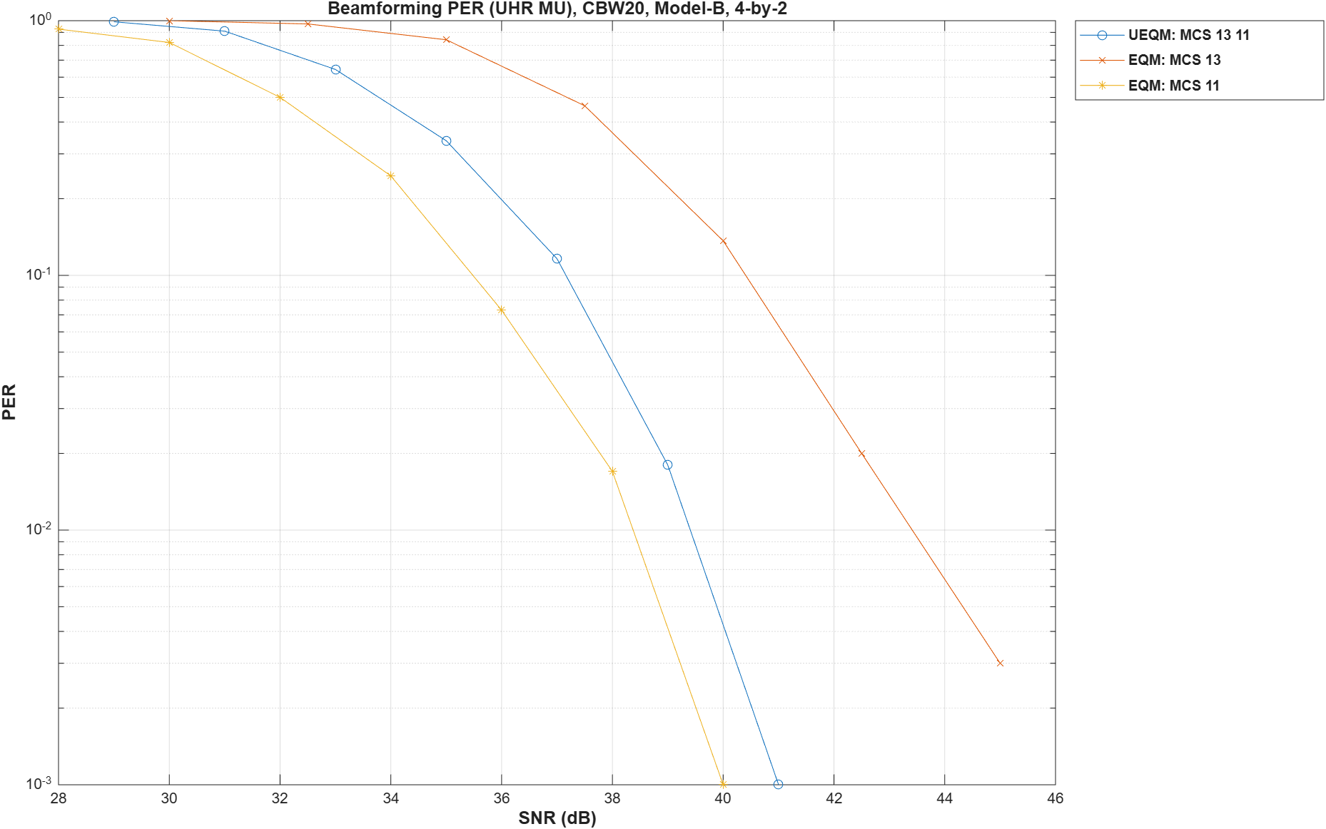
By running a longer simulation with maxNumErrors:1e2 and maxNumPackets:1e3, you can generate the figure below. It shows the PER performance of UEQM and EQM with different MCS combinations. Though the PER performance of UEQM is slightly worse than that of EQM for MCS 11, the overall system throughput can be higher because the high-SNR spatial stream can utilize a higher-order modulation scheme.
Using 4x UHR-LTF compression mode for NDP and data packet transmissions allows all subcarriers to be sounded and the channel to be estimated. When using 2x UHR-LTF compression mode, linear interpolation is performed during channel estimation. This example does not perform subcarrier beamforming smoothing. Therefore, if you configure the simulation to use 2x UHR-LTF compression, the interpolation performed during channel estimation not correctly estimate the beamforming matrix for all subcarriers and the PER increases.
Selected Bibliography
[1] IEEE P802.11bn™/D1.0. IEEE Standard for Information Technology - Telecommunications and Information Exchange between Systems - Local and Metropolitan Area Networks - Specific Requirements - Part 11: Wireless LAN Medium Access Control (MAC) and Physical Layer (PHY) Specifications - Amendment 6: Enhancements for ultra high reliability (UHR).
[2] Ron Porat etc, "Improved Tx Beamforming with UEQM," Accessed Aug 14th, 2025, https://mentor.ieee.org/802.11/dcn/24/11-24-0117-01-00bn-improved-tx-beamforming-with-ueqm.pptx.
[3] IEEE Std 802.11™-2024. IEEE Standard for Information Technology - Telecommunications and Information Exchange between Systems - Local and Metropolitan Area Networks - Specific Requirements - Part 11: Wireless LAN Medium Access Control (MAC) and Physical Layer (PHY) Specifications.