Main Content

wlanEHTMUConfig

Configure EHT MU transmission

Since R2022b

    Description

    The wlanEHTMUConfig object is a configuration object for the WLAN extremely high-throughput multi-user (EHT MU) packet format.

    Creation

    Description

    example

    cfgEHTMU = wlanEHTMUConfig(AllocationIndex) creates cfgEHTMU, a configuration object that initializes transmit parameters for an IEEE® 802.11™ EHT MU PPDU for AllocationIndex, the input resource unit allocation. The PPDU type is OFDMA. For a detailed description of the EHT WLAN format, see [1].

    example

    cfgEHTMU = wlanEHTMUConfig(ChannelBandwidth) creates cfgEHTMU, a configuration object that initializes transmit parameters for an IEEE 802.11 EHT MU PPDU for ChannelBandwidth, the input channel bandwidth. The PPDU type is non-OFDMA.

    example

    cfgEHTMU = wlanEHTMUConfig(___,Name=Value) sets properties using one or more name-value pairs. For example, wlanEHTMUConfig("CBW320",NumUsers=8) specifies a non-OFDMA transmission with eight users and a bandwidth allocation of 320 MHz.

    At runtime, the calling function validates object settings for properties relevant to the operation of the function.

    Properties

    expand all

    Resource unit (RU) allocation index for each 20 MHz subchannel, specified as an integer, row vector of integers, or matrix of integers. This property determines the number of RUs, the size of each RU, the number of users assigned to each RU, and which RUs are punctured. For an example of puncturing in OFDMA transmissions, see 802.11be Waveform Generation.

    The correspondence between allocation indices and resource unit allocations is given in the EHT MU Transmission tutorial. This property applies only when the PPDU type is OFDMA.

    The format of AllocationIndex depends on your desired channel bandwidth.

    • Specify AllocationIndex as an integer to set a channel bandwidth of 20 MHz. For example, specifying AllocationIndex as 0 gives nine RUs, each with one user and of size 26.

    • Specify AllocationIndex as a 1-by-N vector of integers to set a channel bandwidth of 40, 80, 160, or 320 MHz. N is equal to the number of 20 MHz subchannels. For example, specifying AllocationIndex as [0 0] gives 18 RUs, each with one user and of size 26.

    • Specify AllocationIndex as an M-by-N matrix of integers to set a channel bandwidth of 160 or 320 MHz. N is as defined above. M is equal to the number of 80 MHz subblocks. When you specify AllocationIndex as a matrix, all of its rows must be equal.

    Note

    When you specify AllocationIndex as a 1-by-N vector in the 160 MHz or 320 MHz case, the value of the property is set to an M-by-N matrix. M is 2 for 160 MHz and 4 for 320 MHz. The new rows may differ from your original input vector. The difference between the rows means that, in each 80 MHz subblock, a different EHT-SIG content channel carries the allocation information. To comply with the standard [1], the object fills in values of 28, 29, and 30, which indicate EHT-SIG content channels signaling no users. The value of M is equal to the number of 80 MHz subblocks in the channel. When you specify AllocationIndex as a matrix, the rows must be equal: this means that the content channels all carry the same information. The Create Multi-User EHT OFDMA Configuration Objects example shows a specific case.

    Note

    You can set this property only when you create the object. After creation, the object is read-only.

    Data Types: double

    Channel bandwidth of PPDU transmission, specified as one of these values:

    • "CBW20" — Channel bandwidth of 20 MHz

    • "CBW40" — Channel bandwidth of 40 MHz

    • "CBW80" — Channel bandwidth of 80 MHz

    • "CBW160" — Channel bandwidth of 160 MHz

    • "CBW320" — Channel bandwidth of 320 MHz

    Create a non-OFDMA wlanEHTMUConfig object by setting this property. When you create an OFDMA wlanEHTMUConfig object, the AllocationIndex determines this property.

    Note

    You can set this property only when you create the object. After creation, the object is read-only.

    Data Types: char | string

    Number of users in a non-OFDMA configuration, specified as an integer in the range [1, 8].

    Note

    You can set this property only when you create the object. After creation, the object is read-only.

    Data Types: single | double

    Puncturing pattern value for a non-OFDMA configuration, specified as an integer in the range [0, 24]. The correspondence between puncturing patterns and integers in the range [0, 24] is defined in Table 36-30 of [1]. For each channel bandwidth, the default, 0, specifies no puncturing.

    • For channel bandwidths of 20 and 40 MHz, PuncturedChannelFieldValue must be 0 because puncturing is not available at these bandwidths.

    • For an 80 MHz channel bandwidth, PuncturedChannelFieldValue must be in the range [0, 4].

    • For a 160 MHz channel bandwidth, PuncturedChannelFieldValue must be in the range [0, 12].

    Note

    You can set this property only when you create the object. After creation, the object is read-only.

    Data Types: single | double

    Enable EHT DUP mode by setting this property to true or 1. This property applies only to non-OFDMA configurations with channel bandwidths of 80, 160, or 320 MHz.

    Note

    You can set this property only when you create the object. After creation, the object is read-only.

    Data Types: logical

    Puncturing pattern in non-OFDMA configuration, specified as a logical vector. This property depends on the PuncturedChannelFieldValue property, as shown in Table 36-30 of [1].

    If the channel bandwidth is 80 or 160 MHz, the length of the vector is equal to the number of 20 MHz subchannels. If the channel bandwidth is 320 MHz, the length of the vector is equal to the number of 40 MHz subchannels. For each entry of the logical vector, a value of true or 1 means that the subchannel that corresponds to the entry is punctured.

    Note

    This property is read-only and is determined by the value of the PuncturedChannelFieldValue property.

    Data Types: logical

    Transmission properties of each RU and MRU in the transmission, specified as a cell array of wlanEHTRU objects. For an OFDMA wlanEHTMUConfig object, the AllocationIndex property determines the RU property. For a non-OFDMA wlanEHTMUConfig object, the ChannelBandwidth property determines the RU property.

    Data Types: cell

    Transmission properties of each user, specified as a cell array of wlanEHTUser objects. For an OFDMA wlanEHTMUConfig object, the AllocationIndex property determines the User property. For a non-OFDMA wlanEHTMUConfig object, the ChannelBandwidth property determines the User property.

    Data Types: cell

    Number of transmit antennas, specified as a positive integer.

    Data Types: double

    Cyclic shift values, in nanoseconds, of additional transmit antennas for the pre-EHT fields of the waveform. The first eight antennas use the cyclic shift values specified in Table 21-10 of [2]. The remaining L antennas use the values that you specify in this property, where L = NumTransmitAntennas – 8. Specify this property as one of these values:

    • An integer in the range [–200, 0] — the wlanEHTMUConfig object uses this cyclic shift value for each of the L additional antennas.

    • A row vector of length L of integers in the range [–200, 0] — the wlanEHTMUConfig object uses the kth element as the cyclic shift value for the (k + 8)th transmit antenna.

      Note

      If you specify this property as a row vector of length greater than L, the wlanEHTMUConfig object uses only the first L elements. For example, if you set the NumTransmitAntennas property to 16, the wlanEHTMUConfig object uses only the first L = 16 – 8 = 8 elements of this vector.

    Dependencies

    To enable this property, set the NumTransmitAntennas property to a value greater than 8.

    Data Types: double

    Phase rotation values for the pre-EHT portion of the waveform, specified as a row vector of length 16 with entries equal to 1 or -1. This property applies only when the channel bandwidth is 320 MHz. The 16 entries of this property correspond to 20 MHz subchannels in ascending order of frequency, as defined in Equation 36-12 of [1].

    Data Types: double

    Guard range (cyclic prefix) duration for the data field within a packet, in microseconds, specified as 3.2, 1.6, or 0.8.

    Note

    The possible value of this property depends on the EHTLTFType property. For 2 × HE-LTF, the value cannot be 3.2. For 4 × HE-LTF, the value cannot be 1.6.

    Data Types: double

    EHT-LTF compression mode, specified as 2 or 4. These values correspond to the 2 × EHT-LTF and 4 × EHT-LTF compression modes. The EHT-LTF type is defined in Table 36-18 of [1] as:

    • 2 × EHT-LTF — Duration of 6.4 μs. The guard interval duration must be 0.8 μs or 1.6 μs.

    • 4 × EHT-LTF — Duration of 12.8 μs. The guard interval duration must be 0.8 μs or 3.2 μs.

    For more information on the EHT-LTF, see Section 36.3.12.10 of [1].

    Data Types: double

    Number of extra EHT-LTF symbols, specified as a positive integer. This property is the amount by which the number of EHT-LTF symbols exceeds the initial number of EHT-LTF symbols. The initial number of EHT-LTF symbols is determined by the total number of spatial streams, per Table 36-43 in [1]. The sum of NumExtraEHTLTFSymbols and the initial number of EHT-LTF symbols cannot exceed eight.

    Data Types: double

    Modulation and coding scheme (MCS) of the extremely high throughput signal field (EHT-SIG), specified as 0, 1, 3, or 15. These respectively correspond to the EHT-SIG-MCS values 0, 1, 2, and 3 in Table 36-88 of [1].

    Data Types: double

    Uplink indication, specified as a numeric or logical 1 (true) or 0 (false). To indicate that the PPDU is sent on a downlink transmission, set this property to 0 (false). To indicate that the PPDU is sent on an uplink transmission, set this property to 1 (true). This property must be false for OFDMA configurations.

    Data Types: logical

    Basic service set (BSS) color identifier, specified as an integer in the range [0, 63].

    Data Types: double

    Spatial reuse indication, specified as an integer in the range [0, 15].

    Data Types: double

    Duration information for transmit opportunity (TXOP) protection, specified as an integer in the range [0, 8448]. This property represents a duration in microseconds. In the TXOP subfield of the U-SIG field, these durations are represented by integers in the range [0, 127]. Therefore, a duration in microseconds must be converted using the procedure given in Table 36-1 of [1]. The default, [], indicates that no information is specified. In this case, the TXOP subfield of the U-SIG field is set to 127.

    Data Types: double

    Channelization for a 320 MHz channel bandwidth, specified as 1 or 2. A 320 MHz channel has three possible locations for the channel center frequencies. In accordance with Section 36.3.23.2 of [1], when you specify 1, these locations are numbered 31, 95, and 159. When you specify 2, the locations are numbers 63, 127, and 191.

    Data Types: double

    Object Functions

    numPostFECPaddingBitsRequired number of post-FEC padding bits
    packetFormat WLAN packet format
    psduLengthEHT PSDU length
    ruInfoResource unit allocation information
    transmitTimePacket transmission time
    showAllocationResource unit allocation

    Examples

    collapse all

    Create a multi-user EHT configuration object with the allocation index set to 48. This setting specifies an OFDMA configuration with one 106+26-tone MRU and one 106-tone RU in a 20 MHz channel. Both resource units have one user.

    allocationIndex = 48;
    cfgSMRU = wlanEHTMUConfig(allocationIndex);

    Display the properties of the MRU.

    cfgSMRU.RU{1}
    ans = 
      wlanEHTRU with properties:
    
        PowerBoostFactor: 1
          SpatialMapping: direct
    
       Read-only properties:
                    Size: [106 26]
                   Index: [1 5]
             UserNumbers: 1


    Create a multi-user EHT configuration object with the allocation index set to the vector [151 30 30 30 64 64 29 29]. This setting specifies a 996+484-tone MRU and two 242-tone RUs in a 160 MHz channel. The MRU has eight users and the two RUs have one user each.

    allocationIndex = [151 30 30 30 64 64 29 29];
    cfgLMRU = wlanEHTMUConfig(allocationIndex,NumTransmitAntennas=8);
    cfgLMRU.User{9}.NumSpaceTimeStreams=8;
    cfgLMRU.User{10}.NumSpaceTimeStreams=8;

    For multi-user OFDMA transmissions with a channel bandwidth of 160 MHz or higher, the EHT-SIG content channels can carry different information per 80 MHz subblock. For these bandwidths, the read-only property AllocationIndex is a matrix of size M-by-N, where M is the number of 80 MHz subblocks and N is the number of 20 MHz subchannels. In this example M is 2 and N is 8.

    Display the AllocationIndex property.

    disp(cfgLMRU.AllocationIndex); 
       151    30    30    30    28    28    29    29
        30    30    30    30    64    64    29    29
    

    The first and second rows of the matrix correspond to the lower and upper 80 MHz subblocks, respectively. In this configuration:

    • The lower 80 MHz subblock's first content channel signals users 1–8. The second content channel signals no users.

    • The upper 80 MHz subblock's first and second content channels signal users 9 and 10, respectively.

    The second half of the first 80 MHz subblock and the first half of the second 80 MHz subblock have been filled with values of 28, 29, and 30. These values correspond to EHT-SIG content channels with no users signalled.

    Display the properties of the MRU.

    cfgLMRU.RU{1}
    ans = 
      wlanEHTRU with properties:
    
        PowerBoostFactor: 1
          SpatialMapping: direct
    
       Read-only properties:
                    Size: [996 484]
                   Index: [1 4]
             UserNumbers: [1 2 3 4 5 6 7 8]


    Now create a multi-user EHT configuration object with the allocation index set to the 2-by-8 matrix obtained by duplicating the previous allocation index.

    allocationIndex = [allocationIndex;allocationIndex];
    cfg2by8 = wlanEHTMUConfig(allocationIndex,NumTransmitAntennas=8);
    cfg2by8.User{9}.NumSpaceTimeStreams=8;
    cfg2by8.User{10}.NumSpaceTimeStreams=8;

    Display the AllocationIndex property.

    disp(cfg2by8.AllocationIndex);
       151    30    30    30    64    64    29    29
       151    30    30    30    64    64    29    29
    

    In this configuration, in both 80 MHz subblocks, users 1–9 are signaled on content channel 1 and user 10 is signaled on content channel 2.

    Verify that the two configuration objects have the same resource unit allocations.

    isequal(ruInfo(cfgLMRU),ruInfo(cfg2by8))
    ans = logical
       1


    Create a non-OFDMA EHT MU configuration object. Set the channel bandwidth to 320 MHz and the number of users to 2. Specify a punctured channel field value of 20.

    cfg = wlanEHTMUConfig("CBW320",NumUsers=2,PuncturedChannelFieldValue=20);

    Display the puncturing pattern determined by the punctured channel field value.

    cfg.PuncturingPattern
    ans = 1×8 logical array
    
       0   1   0   0   0   0   1   1


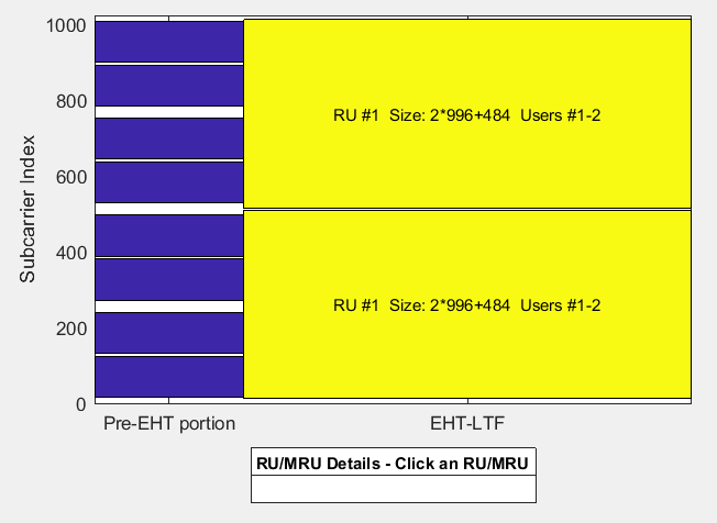
    Show the RU allocation of the configuration. The punctured 40 MHz subchannels do not appear in the figure.

    showAllocation(cfg)

    Figure RU/MRU Assignment and Occupied Subcarriers contains an axes object. The axes object with ylabel Subcarrier Index contains 31 objects of type patch, line, text.

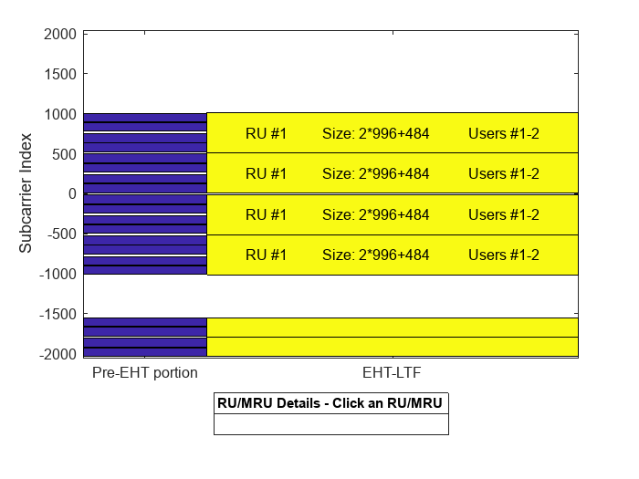
    You can zoom in on an individual 80 MHz subblock by clicking the figure and choosing S1, S2, S3, or S4.

    S3 new icon.png

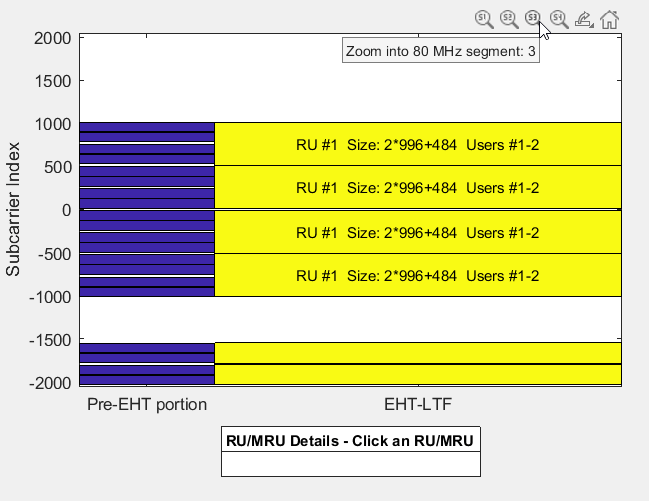
    This is a zoomed-in view of the third segment, which consists of the subcarriers whose index is between 0 and 1000.

    S3 after zoom.png

    References

    [2] IEEE Std 802.11-2020 (Revision of IEEE Std 802.11-2016). “Part 11: Wireless LAN Medium Access Control (MAC) and Physical Layer (PHY) Specifications.” IEEE Standard for Information Technology — Telecommunications and Information Exchange between Systems — Local and Metropolitan Area Networks — Specific Requirements.

    Extended Capabilities

    Version History

    Introduced in R2022b

    expand all