Main Content

filterpadding

Joint time-frequency scattering filter padding

Since R2024b

    Description

    [wav,lowpass] = filterpadding(jtfn) returns structures containing the same first-order time wavelet filter and lowpass filter padded to two different lengths: the empirically determined ideal length, and the length based on the padding factors specified in the joint time-frequency scattering (JTFS) network jtfn. The wav structure contains the padded wavelet filters, and the lowpass structure contains the padded lowpass filters. The JTFS network uses the filters of minimum length.

    You can use filterpadding to determine which padded length is sufficient for your application.

    [wav,lowpass] = filterpadding(jtfn,Name=Value) specifies options using one or more name-value arguments. You can add these arguments to the previous syntax. For example, to specify the frequency wavelets, set FilterBank to "frequency".

    example

    Examples

    collapse all

    Create a joint time-frequency scattering network. Specify a signal length of 1025.

    jtfn = timeFrequencyScattering(SignalLength=1025);

    Obtain the ideal and padded wavelet and lowpass (scaling) filters from the second-order wavelet time filter bank. The ideal filters are the lowest-frequency wavelet and lowpass filters padded so that they decay properly. The JTFS network determines this pad length empirically. The padded filters are the lowest-frequency wavelet and lowpass filters padded to a length of 2^ceil(log2(jtfn.SignalLength)+jtfn.TimeMaxPaddingFactor).

    [wav,lowpass] = filterpadding(jtfn,FilterBank="time",NumFilterBank=2)
    wav = struct with fields:
                    PaddedLength: 2560
                        IdealPad: [2560×1 double]
                   PaddingFactor: [8192×1 double]
             IdealPadDownsampled: [20×1 double]
        PaddingFactorDownsampled: [64×1 double]
    
    
    lowpass = struct with fields:
                    PaddedLength: 2560
                        IdealPad: [2560×1 double]
                   PaddingFactor: [8192×1 double]
             IdealPadDownsampled: [20×1 double]
        PaddingFactorDownsampled: [32×1 double]


    Ideal and Padded Filters

    Plot the ideal and padded wavelet filters in the time domain. Because the wavelets are complex valued, plot their real and imaginary parts, and their magnitude separately. The helper function helperPlotPaddedFilters does this for you. The source code for the function is in the same folder as this example file.

    helperPlotPaddedFilters("wavelet",wav,"notDownsampled")

    Figure contains 2 axes objects. Axes object 1 with title Ideal Wavelet Boundary Values: [4.532e-07 4.5324e-07] contains 3 objects of type line. These objects represent Real, Imaginary, Magnitude. Axes object 2 with title Padded Wavelet Boundary Values: [0 1.3553e-20] contains 3 objects of type line.

    You can use the same helper function to plot the magnitude of the ideal and padded lowpass filters.

    helperPlotPaddedFilters("lowpass",lowpass,"notDownsampled")

    Figure contains 2 axes objects. Axes object 1 with title Ideal Lowpass Boundary Values: [6.0798e-07 6.0803e-07] contains an object of type line. Axes object 2 with title Padded Lowpass Boundary Values: [0 1.0842e-19] contains an object of type line.

    Because the ideal filters are shorter than the padded filters, the network will use the ideal filters for the JTFS transform. Create a second JTFS network for a signal length of 262,144. Set the filter data type to single precision and the time maximum padding factor to 0. Inspect the sizes of the ideal and padded wavelet filters. The padded filter length is equal to the signal length, while the ideal filter length is almost twice as large as the signal length. Unlike the first network, this network will use the padded filters for the JTFS transform. By setting the padding factor to zero, you minimize memory usage and improve computational efficiency.

    jtfn2 = timeFrequencyScattering(SignalLength=2^18, ...
        TimeMaxPaddingFactor=0, ...
        FilterDataType="single");
    [wav2,lowpass2] = filterpadding(jtfn2);
    wav2
    wav2 = struct with fields:
                    PaddedLength: 262144
                        IdealPad: [458752×1 single]
                   PaddingFactor: [262144×1 single]
             IdealPadDownsampled: [28×1 single]
        PaddingFactorDownsampled: [16×1 single]


    Plot the filters. Depending on your application, the padded filter decay may be sufficient for your purposes.

    helperPlotPaddedFilters("wavelet",wav2,"notDownsampled")

    Figure contains 2 axes objects. Axes object 1 with title Ideal Wavelet Boundary Values: [1.0394e-12 1.0714e-12] contains 3 objects of type line. These objects represent Real, Imaginary, Magnitude. Axes object 2 with title Padded Wavelet Boundary Values: [2.1557e-08 2.1557e-08] contains 3 objects of type line.

    Downsampled Ideal and Padded Filters

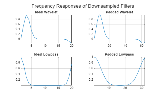
    To determine which padded length is sufficient for your application, you can also view the frequency responses of the maximally downsampled ideal and padded filters. Plot the frequency responses of the downsampled ideal and padded wavelet filters of the first JTFS network. The helper function helperPlotDownsampledFrequencyResponses does this for you. The source code for the function is in the same folder as this example file.

    helperPlotDownsampledFrequencyResponses(wav,lowpass)

    Figure contains 4 axes objects. Axes object 1 with title Ideal Wavelet contains an object of type line. Axes object 2 with title Padded Wavelet contains an object of type line. Axes object 3 with title Ideal Lowpass contains an object of type line. Axes object 4 with title Padded Lowpass contains an object of type line.

    You can use helperPlotPaddedFilters to plot the same filters in the time domain.

    helperPlotPaddedFilters("wavelet",wav,"downsampled")

    Figure contains 2 axes objects. Axes object 1 with title Ideal Wavelet Boundary Values: [5.8009e-05 0.00016333] contains 3 objects of type line. These objects represent Real, Imaginary, Magnitude. Axes object 2 with title Padded Wavelet Boundary Values: [0 7.7579e-18] contains 3 objects of type line.

    helperPlotPaddedFilters("lowpass",lowpass,"downsampled")

    Figure contains 2 axes objects. Axes object 1 with title Ideal Lowpass Boundary Values: [7.7821e-05 0.00019653] contains an object of type line. Axes object 2 with title Padded Lowpass Boundary Values: [0 5.2042e-18] contains an object of type line.

    Input Arguments

    collapse all

    Joint time-frequency scattering network, specified as a timeFrequencyScattering object.

    Name-Value Arguments

    Specify optional pairs of arguments as Name1=Value1,...,NameN=ValueN, where Name is the argument name and Value is the corresponding value. Name-value arguments must appear after other arguments, but the order of the pairs does not matter.

    Example: FilterBank="frequency",NumFilterBank=2 specifies the spin-down wavelets.

    JTFS filter bank type, specified as one of the following:

    • "time" — Wavelet time filter bank

    • "frequency" — Wavelet frequency filter bank

    JTFS filter bank number, specified as either 1 or 2. If FilterBank is "time", then 1 and 2 refer to the first- and second-order wavelet time filter banks, respectively. If FilterBank is "frequency", then 1 and 2 refer to the spin-up and -down wavelets, respectively.

    Output Arguments

    collapse all

    Ideal and padding factor wavelet filters associated with the specified FilterBank and NumFilterBank, returned as a structure with these fields:

    • PaddedLength — Length of the filter the network uses

    • IdealPad — Frequency response of the wavelet filter padded by the empirically determined ideal length

    • PaddingFactor — Frequency response of the wavelet filter padded by the length derived from the padding factor

    • IdealPadDownsampled — Frequency response of the maximally downsampled IdealPad wavelet filter

    • PaddingFactorDownsampled — Frequency response of the maximally downsampled PaddingFactor wavelet filter

    For more information, see IdealPad and PaddingFactor Filters.

    Ideal and padding factor lowpass filters associated with the specified FilterBank and NumFilterBank, returned as a structure with these fields:

    • PaddedLength — Length of the filter the network uses

    • IdealPad — Frequency response of the lowpass filter padded by the empirically determined ideal length

    • PaddingFactor — Frequency response of the lowpass filter padded by the length derived from the padding factor

    • IdealPadDownsampled — Frequency response of the maximally downsampled IdealPad lowpass filter

    • PaddingFactorDownsampled — Frequency response of the maximally downsampled PaddingFactor lowpass filter

    For more information, see IdealPad and PaddingFactor Filters.

    More About

    collapse all

    IdealPad and PaddingFactor Filters

    The IdealPad filters are the lowest-frequency wavelet and lowpass (scaling) filters padded so that they decay properly. The JTFS network jtfn determines empirically this pad length. The PaddingFactor filters are the lowest-frequency wavelet and lowpass (scaling) filters padded by a length determined from the TimeMaxPaddingFactor and FrequencyMaxPaddingFactor properties.

    The JTFS network uses the filters of minimum length. If the ideal pad is more than twice the length derived from the padding factor, the JTFS network issues a warning message. To learn how to compare the wavelet decay of the IdealPad and PaddingFactor filters, see Effects of Padding Factor on Wavelet Filter Decay.

    Version History

    Introduced in R2024b

    See Also

    Objects

    Functions