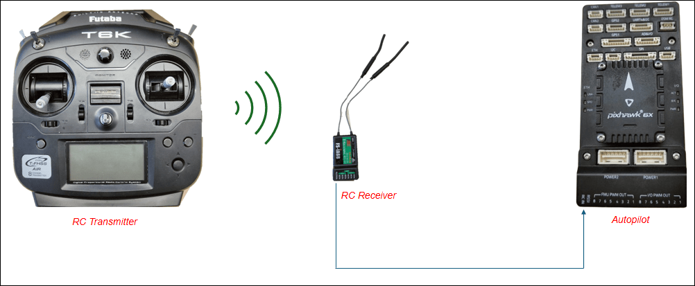
Verify RC Transmitter Input with RC Receive Block
This example shows how to use the UAV Toolbox Support Package for ArduPilot® Autopilots to test your RC transmitter with the RC Receive block in Simulink®. You can verify RC functionality on both the host target (simulation environment) and ArduPilot-based flight controller hardware. You also learn to read and interpret both raw and normalized channel data with trim and deadzone settings applied. Additionally, you monitor various vehicle statuses.
The RC Receive block used in this example reads RC channel data transmitted from your RC transmitter. It supports up to 16 RC channels, and provides access to additional vehicle and status information from the flight controller.
Using this example, you can:
Read raw RC channel data into Simulink from a Pixhawk flight controller.
Monitor status information such as flight mode, RSSI, arming status, and emergency stop state.
Apply trimming and deadzone settings to RC inputs using ArduPilot’s onboard configuration.
Test RC input in both hardware and simulation (host target) environments.
For more information on the compatible RC protocols, see Radio Control Systems — Copter documentation.
Prerequisites
Before you begin, complete the following.
If you are new to Simulink, watch the Simulink Quick Start video.
If you have not done so already, complete the steps in Install UAV Toolbox Support Package for ArduPilot Autopilots in Windows.
You must install Mission Planner for hardware calibration and configuration.
Required Hardware
ArduPilot-Compatible flight controller. This example uses Pixhawk 6x.
USB cable
RC Receiver. This example uses FS-i6. Any RC receiver and transmitter supported by ArduPilot protocols can be used.
RC Transmitter. This example uses FS-i6.
Read RC Channel Data Using ArduPilot-Compatible Hardware
Connect your ArduPilot-compatible flight controller to Simulink and read channel data using the RC Receive block.
Note: Ensure your RC transmitter and receiver are properly bound before starting.
Set Up Hardware and Verify RC Input in Mission Planner
Perform these steps to connect your hardware and verify RC communication.
1. Connect Pixhawk 6x to your host Computer using a USB cable.
2. Connect the SBUS pins of the RC Receiver to the RC IN port of Pixhawk 6x, as shown in this image.
3. Launch Mission Planner on your host computer and click Connect to establish a connection with the flight controller.
4. Calibrate the RC receiver.
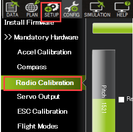
i. In Mission Planner. go to Setup > Radio Calibration.
ii. Perform the steps mentioned in the Radio Control Calibration — Copter documentation.
iii. Move the sticks and switches on your RC transmitter and verify that the green channel bars respond in real time.
5. Complete the calibration process as prompted.
This process sets the following RC input parameters for each channel (1–16):
- RCx_MIN (minimum PWM)
- RCx_MAX (maximum PWM)
- RCx_TRIM (neutral point)
(where x is the channel number, 1–16)
RC Receiver Setup Tips
If Mission Planner does not detect your RC input:
Check the
RC_PROTOCOLSparameter and enable your receiver's protocol. Set it to1to automatically detect supported protocols.Check the
RC_OPTIONSparameter and ensure the Ignore RC Receiver option is not selected.
Configure and Run Simulink Model
Perform these steps to set up your Simulink model to receive and interpret RC input.
1. Create a new Simulink model.
Open MATLAB®.
On the Home tab, click the Simulink button.
In Simulink, select Blank Model, and then click Create Model to open a new model window.
2. Add RC Receive block.
Double-click anywhere in the model canvas. In the quick insert menu that appears, enter RC Receive. A list of blocks appears. Verify that the RC Receive block from the UAV Toolbox Support Package for ArduPilot Autopilots library is selected. Check the library name listed under the block name and the block description in the pane to the right of the search results.
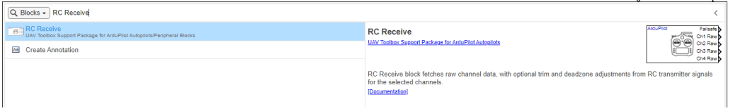
In the Library Browser, navigate to UAV Toolbox Support Package for ArduPilot Autopilots > RC Receive, and add it to the model.
3. Configure the Simulink model to use Pixhawk 6x.
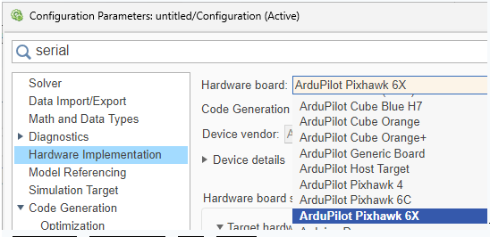
i. In the Simulink model, go to Modeling> Model Settings.
ii. In the Configuration Parameters dialog box, navigate to Hardware Implementation > Hardware board and select ArduPilot Pixhawk 6x from the dropdown.
iii. Click Apply and OK.
4. Set Up RC Channels in the Block.
By default, channels 1–4 are included.
Add or remove channels using the Add or Delete buttons in the block dialog.
5. Choose Channel Data Type. In most workflows, select Using trim & deadzone. This option applies the RC trim, deadzone, and scaling parameters configured in Mission Planner, allowing you to verify RC behavior as it is interpreted by the flight controller during operation. Select Raw Data only if you require direct access to unprocessed PWM values or if you plan to implement trimming and deadzone logic manually in your Simulink model.
Raw Channel Data: The unprocessed PWM value received from the RC transmitter.
Trim & Deadzone Applied Data: The raw values processed according to the trim (
RCx_TRIM) and deadzone (RCx_DZ) parameters set in Mission Planner (see Config > Full Parameter List).
Note: If you have already set trims on your RC transmitter and do not intend to use the parameters, select Raw Data.
6. Verify the trim and deadzone output from the RC Receive block by comparing it with the calculated value using the formula provided on RC Receive.
7. Configure Additional Vehicle Status Outputs.
In the RC Receive block parameters dialog box, click Advanced and select the additional outputs. In this example, the options to output Flight Mode, Arming Status, and Emergency Stop Status are already selected.
8. Set Up Flight Mode switching.
i. In the Mission Planner, assign the FLTMODE_CH parameter to the desired RC channel for flight mode switching.
ii. Click Write Params to save the change.
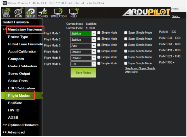
iii. Go to Setup > Mandatory Hardware > Flight Modes in Mission Planner to map flight modes to different RC input ranges. This allows you to map specific flight modes to different ranges of values on the assigned RC channel.
The block outputs the flight mode index (starting from 0) corresponding to your Mission Planner configuration. For more information, see RC Receive.
Note: If the requested flight mode change does not take effect on the flight controller (for example, due to an invalid RC input range or a configuration mismatch), the RC Receive block continues to output the previously active flight mode.
9. Configure Arming and Emergency Stop.
In Mission Planner, go to Config> User Params.
Assign the Arm/Disarm (4.2 and higher) and Motor Emergency Stop options to different RC channels.
These functions trigger ON when the RC channel value reaches maximum and OFF at minimum.
In this example, arming is assigned to channel
5and emergency stop to channel6.
- The arm output is 1 when armed, 0 when disarmed.
- The emergency stop output is 1 when active, 0 otherwise.
10. Disconnect Mission Planner and perform Monitor & Tune action.
i. In Simulink model, go to the Hardware tab.
ii. Click Monitor & Tune to run the model and connect to your hardware.
11. Test RC Inputs and Vehicle Status.
Vary RC channel inputs on your transmitter and observe the corresponding channel values and vehicle status outputs in real time.
By default, the RC Receive block outputs the failsafe status. To test, turn off the RC transmitter while the model is running; the failsafe output should switch to
1.
Use RC Receive Block in ArduPilot Host Target Mode
You can test your Simulink model and RC Receive block in simulation mode, without needing physical flight controller hardware. This is known as Host Target mode.
1. Set the Hardware Board to Host Target.
In the Simulink model, click Modeling > Model Settings.
In the Configuration Parameters dialog, navigate to Hardware Implementation > Hardware board.
Select Host Target from the hardware board dropdown.
2. Connect to Mission Planner.
Run your Simulink model and open Mission Planner.
Mission Planner should connect automatically via UDP.
If the connection does not occur automatically, manually connect Mission Planner to the correct UDP port used by the model.
3. Read and verify the following RC data.
RC channel data.
Flight mode
Arming status
Emergency stop status
The workflow for reading and interpreting these signals is the same as when using hardware.
Emulate RC Receiver Input in SITL
In Software-in-the-Loop (SITL) simulation, there is no physical RC transmitter or receiver. Instead, you must emulate RC channel inputs to test your Simulink model and vehicle behavior. There are two primary methods:
Option1: Use MAVProxy Terminal
Use the MAVProxy console to directly set RC channel values. For example, enter
rc 3 1700to set the output of RC channel 3 to 1700 in the Simulink block.Use this method to manually set or script RC channel values for testing.
Option 2: Use a Joystick via Mission Planner
Connect a joystick or gamepad to your computer and configure Mission Planner to use it as an RC input device for SITL.
For setup instructions, see Joystick/Gamepad — Copter documentation. This method provides a more realistic piloting experience and is ideal for interactive testing.
Other Things to Try
Try running the same model in Connected IO mode to visualize RC block outputs without deploying to hardware. This mode allows real-time interaction with your model while keeping Simulink on the host computer. For more information on Connected IO mode, see Communicate with Hardware Using Connected I/O.