このページは機械翻訳を使用して翻訳されました。元の英語を参照するには、ここをクリックします。
指定された周波数とデューティサイクルのePWM波形を生成する
この例では、タイムベース、カウンタ比較、アクション修飾子サブモジュールを使用して、指定された周波数とデューティ サイクルのePWM波形を生成する方法を示します。
この例では、次を行う方法を学びます。
アップカウントおよびアップダウンカウント動作モードで指定された周波数のePWM波形を生成します。
必要なデューティ サイクルを実現します。
前提条件
次のチュートリアルを完了してください。
必要なハードウェア
TI Delfino F28379DLaunchPad
ハードウェアの接続
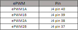
F28379D LaunchPadハードウェアの次のピンで、オシロスコープでePWM波形を表示できます。
利用可能なモデル
モデル
f2837xePWMGettingStarted.slx モデルを開きます。
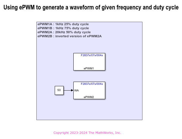
ePWM1 は、10 kHz の周波数の波形を生成するように構成されています。
ePWM2 は、20 kHz の周波数の波形を生成するように構成されています。
モデルの設定
1. モデルを開きます。この例のモデルは、TI Delfino F28379D LaunchPadハードウェア用に構成されています。
2. 他の TI C2000 プロセッサでモデルを実行するには、Ctrl+E を押して [構成パラメーター]ダイアログ ボックスを開きます。次に、ハードウェア実装 > ハードウェアボード に移動して、ハードウェアボードを選択します。
3. ターゲット ハードウェア リソース > ePWM に移動して、必要なePWM周波数を設定します。適用 をクリックし、次に OK をクリックします。
周波数とデューティサイクルの計算
1. この例では、構成設定 Sysclk/2 に基づくePWMクロックの周波数は 100 MHz です。
2. ePWM1 出力は、10 kHz の周波数の出力波形を取得するように構成されています。これは、ePWM Type 1-4 ブロックの次の構成によって実現されます。
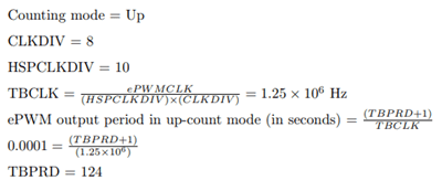
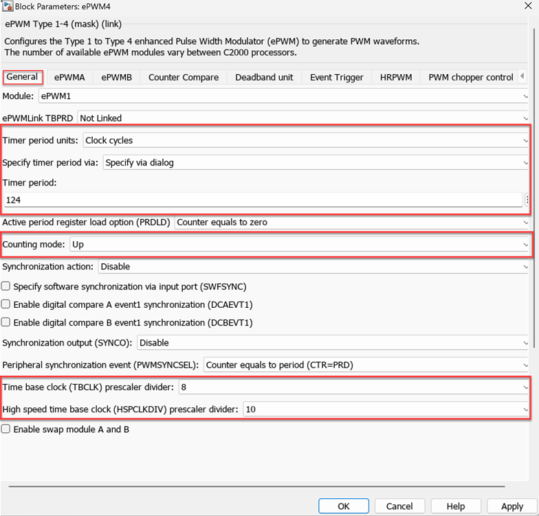
4. ePWMA 波形は CMPAアクションによって生成され、ePWMB 波形は CMPBアクションによって生成されます。このアクション修飾子の構成に基づくと、デューティ サイクルが 25% の場合、CMPA 値は TBPRD の 25% になり、デューティ サイクルが 75% の場合、CMPB 値は TBPRD の 75% になります。
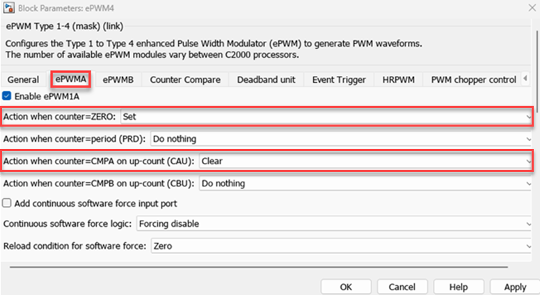
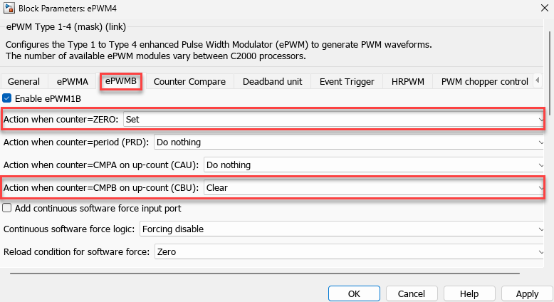
5. この画像の構成では、ePWM2 の出力周波数 20 kHz を実現します。ePWM2 はアップダウン モードに設定されているため、周期は目的の周波数の半分になります。
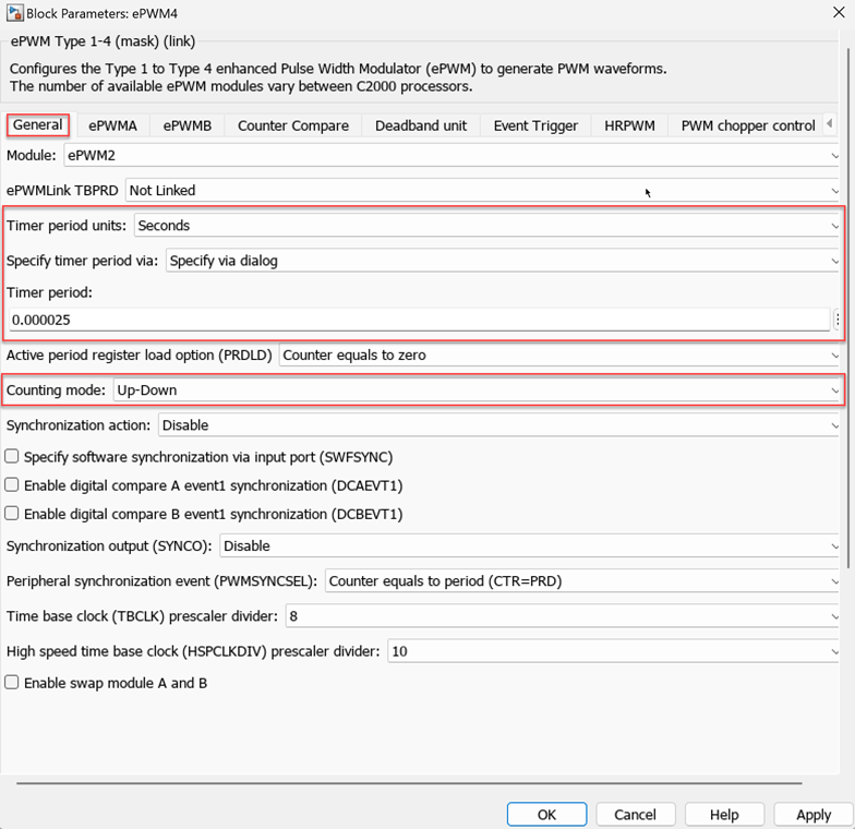
タイマー期間のカウント モードの詳細については、「Timer period」を参照してください。
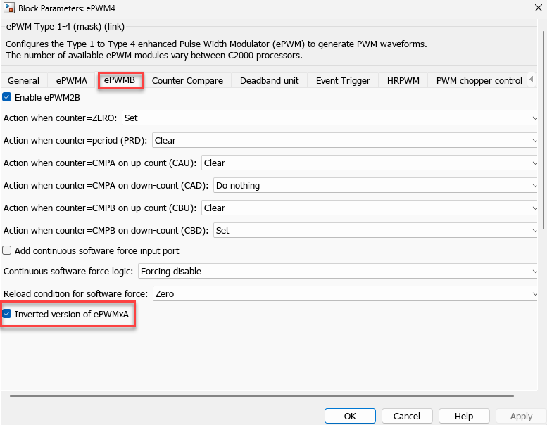
6. この画像に示すデフォルトのアクション修飾子設定では、ePWM2A の必要なデューティ サイクルが入力ポートを介してパーセンテージで提供されます。
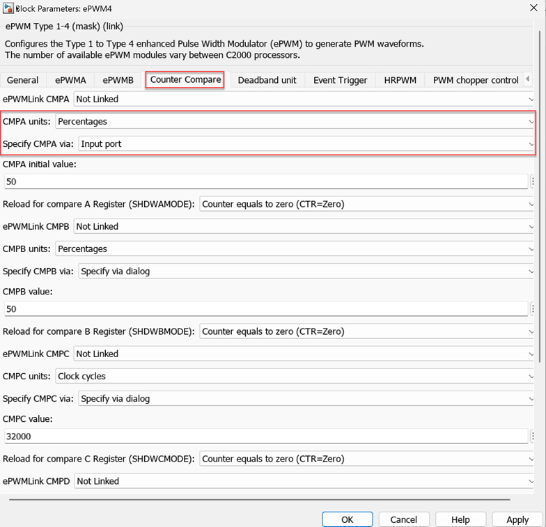
7. ここに示すように、ePWM2A の反転バージョンとして ePWM2B を選択します。
モデルを実行
1. [ビルド]、[[デプロイと開始]] ([ハードウェア] タブ) をクリックするか、[Ctrl+B] を押して、実行可能ファイルをビルドし、ターゲットにダウンロードします。
2. 発振器を J4 ピン 37 ~ 40 に接続します。
3. 次のePWM波形を観察します。
GPIO0 (J4 ピン 40) の ePWM1A は、デューティ サイクルが 25% の 1 kHz 信号です。
GPIO1 (J4 ピン 39) の ePWM1B は、デューティ サイクルが 75% の 1 kHz 信号です。
GPIO2 (J4 ピン 38) の ePWM2A は、デューティ サイクルが 50% の 20 kHz 信号です。
GPIO3 (J4 ピン 37) の ePWM2B は、ePWM2A の反転バージョンです。
その他の試行
あるいは、eCAP ブロックを使用してePWM信号をキャプチャし、Scope ブロックを使用して信号を表示することもできます。
さまざまな周波数とデューティ サイクルの波形を生成してみてください。
ダウンカウント動作モードで波形を生成してみます。