E3xx Receiver
Add-On Required: This feature requires the Communications Toolbox Support Package for USRP Embedded Series Radio add-on.

Libraries:
Communications Toolbox Support Package for USRP Embedded Series Radio /
E3xx
Description
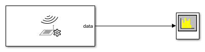
The E3xx Receiver block receives data from a USRP™ E3xx radio hardware.
The block supports these radio hardware devices:
USRP E310
USRP E312
You can use the E3xx Receiver block to simulate and develop various software-defined radio (SDR) applications. This diagram shows the conceptual overview of transmitting and receiving radio signals in Simulink® using the Communications Toolbox™ Support Package for USRP Embedded Series Radio. Simulink interacts with the E3xx Receiver block to receive signals from the radio hardware.

Ports
Input
center frequency — External RF center frequency
nonnegative finite scalar
External RF center frequency, specified as a nonnegative finite scalar. The valid center frequency range is from 70 MHz to 6 GHz.
Dependencies
To enable this port, set the Source of center frequency parameter to Input port.
Data Types: double
gain — External gain
numeric scalar | 1-by-2 numeric vector
External gain, specified as a numeric scalar or a 1-by-2 numeric vector. The valid gain range is from –10 dB to 73 dB and depends on the center frequency. An incompatible gain and center frequency combination returns an error from the radio hardware. For the acceptable minimum and maximum gain values per center frequency, check the manufacturer's specification.
Set the gain based on the Channel mapping parameter configuration.
For a single channel, specify the gain as a scalar.
For two channels that use the same gain value, specify the gain as a scalar. The block applies the gain by scalar expansion.
For two channels that use different gain values, specify the gain as a 1-by-2 vector. The ith element of the vector is applied to the ith channel specified by the Channel mapping parameter.
Dependencies
To enable this port, set the Source of gain parameter to
Input port.
Data Types: double
Output
data — Output signal
complex matrix
Output signal received from the radio hardware, returned as a complex matrix. The number of columns in the matrix depends on the number of channels in use, as specified by the Channel mapping parameter. Each column corresponds to a channel of complex data received on one channel.
This port supports complex values with these data types:
16-bit signed integers — Complex values are the raw 16-bit I and Q samples from the board. The 12-bit value from the ADC of the AD9361 RF chip is sign-extended to 16 bits.
Single-precision floating point — Complex values are scaled to the range of [–1, 1]. The block derives this value from the sign-extended 16 bits received from the board.
Double-precision floating point — Complex values are scaled to the range of [–1, 1]. The block derives this value from the sign-extended 16 bits received from the board.
To specify the data type, use the Output data type parameter.
To qualify data reception, use the data valid port. The first valid data frame can contain transient values, resulting in packets containing undefined data.
Data Types: int16 | single | double
Complex Number Support: Yes
data valid — Valid data indicator
1 | 0
Valid data indicator, returned as one of these values:
1indicates that the block has received data from the radio hardware.0indicates that the block has not received data from the radio hardware.
Dependencies
To enable this port, on the Advanced tab, update
Data timeout (sec) to a value other than
Inf.
Data Types: Boolean
overflow — Data discontinuity flag
1 | 0
Data discontinuity flag, returned as one of these values:
1indicates the presence of overflow resulting in noncontiguous data.0indicates no overflow.
You can use this port as a diagnostic tool to determine real-time operation of the E3xx Receiver block. If your model is not running in real time, increase the frame size to approach or achieve real-time performance. Alternatively, you can decrease the baseband sampling rate.
Dependencies
To enable this port, on the Main tab, select the Enable output port for overflow indicator parameter.
Data Types: Boolean
Parameters
The E3xx Receiver block supports up to two channels to receive data from the E3xx radio hardware. Use the Channel mapping parameter to indicate whether to use a single channel or two channels. For each channel in the output signal, data, you can set the Gain (dB) parameter independently, or you can apply the same setting to all channels. All other parameter values are applied to each channel in use.
To check connectivity between the block and the radio hardware, and to synchronize radio settings between them, on the Main tab, click Info.
When you set block parameter values, the E3xx Receiver block first checks that the values have the correct data types. If the values pass those checks, the values can still be out of range for the radio hardware. In that case, the radio hardware sets the actual value as close to the specified value as possible. When you next synchronize the block with the radio hardware by clicking Info, a dialog box displays the actual values.
If a parameter is listed as tunable, then you can change its value during simulation.
Main TabRadio IP address — IP address of radio hardware
192.168.3.2 (default) | dotted-quad expression
IP address of the radio hardware, specified as a dotted-quad expression.
This parameter must match the physical IP address of the radio hardware assigned during hardware setup. For more information, see Guided Host-Radio Hardware Setup. If you configure the radio hardware with an IP address other than the default, update Radio IP address accordingly.
Source of center frequency — Source of center frequency
Dialog (default) | Input port
Source of center frequency, specified as one of these options:
Dialog— Set the center frequency by using the Center frequency (Hz) parameter.Input port— Set the center frequency by using the center frequency input port.
Center frequency (Hz) — RF center frequency in Hz
2.4e9
(default) | nonnegative scalar
RF center frequency in Hz, specified as a nonnegative scalar. The valid range for center frequency is 70 MHz to 6 GHz.
Tunable: Yes
Dependencies
To enable this parameter, set the Source of center frequency
parameter to Dialog.
Data Types: double
Source of gain — Choose source of gain
AGC Slow
                                                  Attack
(default) | AGC Fast Attack | Dialog | Input port
AGC Slow Attack— For signals with slowly changing power levels.AGC Fast Attack— For signals with rapidly changing power levels.Dialog— Specify the gain by using the Gain (dB) parameter.Input port— Specify the gain by using the gain input port.
Gain (dB) — Gain
10 (default) | numeric scalar | 1-by-2
numeric vector
Gain in dB, specified as a numeric scalar or a 1-by-2 numeric vector. The valid gain range is from –10 dB to 73 dB and depends on the center frequency. An incompatible gain and center frequency combination returns an error from the radio hardware. For the acceptable minimum and maximum gain values per center frequency, check the manufacturer's specification.
Set the gain value based on the Channel mapping parameter configuration.
For a single channel, specify the gain as a scalar.
For two channels that use the same gain value, specify the gain as a scalar. The block applies the gain by scalar expansion.
For two channels that use different gain values, specify the gain as a 1-by-2 vector. The ith element of the vector is applied to the ith channel specified by the Channel mapping parameter.
Tunable: Yes
Dependencies
To enable this parameter, set the Source of gain parameter to
Dialog.
Data Types: double
Channel Mapping — Channel output mapping
1 (default) | 2 | [1 2]
Channel output mapping, specified as a scalar or a 1-by-2 vector:
1— Only channel 1 is in use.2— Only channel 2 is in use.[1 2]— Both channels are in use.
Baseband sample rate (Hz) — Baseband sampling rate in Hz
1e6
(default) | positive scalar
Baseband sampling rate in Hz, specified as a positive scalar. The valid range of this parameter is 520.834 kHz to 30.72 MHz.
Note
To synchronize the block with the radio hardware, on the Menu tab, click Info. If the specified and actual rates have a small mismatch, verify that the computed rate is close to the value you actually want.
Data Types: double
Output data type — Complex data type on data port
int16 (default) | single | double
Select output data type, as one of these options:
int16— Integer values are the raw 16-bit I and Q samples from the board. The 12-bit value from the ADC of the AD9361 RF chip is sign-extended to 16 bits.single— Single-precision floating point values are scaled to the range of [–1, 1]. The block derives this value from the sign-extended 16 bits received from the board.double— Double-precision floating point values are scaled to the range of [–1, 1]. The block derives this value from the sign-extended 16 bits received from the board.
Samples per frame — Number of samples per frame
20000 (default) | positive integer
Number of samples per frame, specified as a positive integer. In single-channel mode, the number of samples per frame must be even. When streaming to the host, using large frame sizes can give more efficient performance. To determine real-time operation of the object, use the overflow output port.
Enable output port for overflow indicator — Enable overflow control signal
on (default) | off
Select this parameter to enable the overflow output port during host-radio hardware data transfers.
Enable burst mode — Enable burst mode
off (default) | on
When you select this parameter, the block produces a set of contiguous frames. This setting can help simulate models that cannot run in real time. When you enable burst mode, specify the amount of contiguous data by using the Frames in burst parameter. For more information on how to use this parameter, see Burst Mode.
Frames in burst — Number of frames in a contiguous burst
1 (default) | positive integer
Number of frames in a contiguous burst, specified as a positive integer.
Dependencies
To enable this parameter, select the Enable burst mode parameter.
Data Types: double
Use custom filter — Enable custom filter
off (default) | on
When you select this parameter, the filter chain uses a custom filter design instead of the default filter design. For example, if the gain or bandwidth characteristics of the default filter does not satisfy the requirements for your application, you can design a custom filter that meets your specific requirements. If the E3xx Receiver block does not have a custom filter design applied yet, click on Launch filter wizard to open the ADI filter wizard. The wizard enables you to design a custom filter for the Analog Devices® AD9361 RF chip based on the Baseband sample rate (Hz) parameter. You can adjust and optimize the settings for calculating the analog filters, interpolation and decimation filters, and FIR coefficients. When you finish with the wizard, to apply the custom filter design to the block, click Apply on the block mask.
Note
When applying a custom filter to the E3xx Receiver block by using the ADI filter wizard, Use custom filter is automatically selected. To switch between the default and your custom filter design, clear or select Use custom filter, respectively. Then click Apply on the block mask.
For more information, see Baseband Sampling Rate and Filter Chains.
Bypass user logic — Enable bypassing user logic
off (default) | on
Select this parameter to enable the radio hardware data path to bypass the algorithm generated and programmed during FPGA targeting or hardware-software co-design. For more information, see FPGA Targeting Workflow and Hardware-Software Co-Design Workflow.
Enable quadrature correction — Quadrature correction
on (default) | off
When you select this parameter, the block applies in-phase and quadrature (IQ) imbalance compensation.
Enable RF DC correction — RF DC correction
on (default) | off
When you select this parameter, the block applies an RF direct current (DC) blocking filter.
Enable baseband DC correction — Baseband DC correction
on (default) | off
When you select this parameter, the block applies a baseband DC blocking filter.
Override automatic sample time — Change sample time of the block
off (default) | on
When you select this parameter, you can change the sample time of the block, by using the Sample time parameter. For more information, see SDR Receiver Sample Times.
Sample time — Sample time of the block
0.02 (default) | positive scalar
Sample time of the block, specified as a positive scalar. The default value corresponds to Samples per frame divided by Baseband sample rate (Hz). Consider changing the default value only when deploying a hardware-software co-design implementation.
Dependencies
To enable this parameter, select the Override automatic sample time parameter.
Data timeout (sec) — Timeout for I/O operations in seconds
Inf (default) | nonnegative scalar
Timeout for I/O operations in seconds, specified as one of these options:
Inf— The block waits indefinitely to complete I/O operations.Nonnegative scalar, N — The block waits N seconds to complete I/O operations. Zero seconds corresponds to a non-blocking setup.
Data Types: double
Loopback — Built-in self-test (BIST) loopback mode
Disabled (default) | Digital Tx -> Digital Rx | RF Rx -> RF Tx
Built-in self-test loopback mode, specified as one of these options:
Disabled— Disable BIST loopback.Digital Tx -> Digital Rx— Enable digital signals to loop back within the device. The signals bypass the RF stage.RF Rx -> RF Tx— Enable incoming receiver RF signals to loop back to the RF transmitter port. The signals bypass the FPGA.
Test signal injection — BIST signal injection mode
Disabled (default) | Tone Inject Tx | Tone Inject Rx
BIST signal injection mode, specified as one of these values:
Disabled— Disable BIST signal injection.Tone Inject Tx— Enable BIST signal injection to transmit path.Tone Inject Rx— Enable BIST signal injection to receive path.
When you enable BIST signal injection, you can set the source of BIST signal generation with the Signal generator mode parameter.
Signal generator mode — Source of BIST signal generation
PRBS (default) | Tone
Source of BIST signal generation, specified as one of these options:
PRBS— Use the pseudo random binary sequence (PRBS) generator of the board.Tone— Use the tone generator of the board. To set the tone frequency and tone level, use the Tone frequency (Hz) and Tone level (dB) parameters, respectively.
Dependencies
To enable this parameter, set the Test signal injection
parameter to Tone Inject Tx or Tone Inject
Rx.
Tone frequency (Hz) — BIST tone frequency
Fs/32 (default) | Fs/16 | Fs*3/32 | Fs/8
BIST tone frequency, specified as
Fs/32, Fs/16,
Fs*3/32, or Fs/8.
Dependencies
To enable this parameter, set the
Signal generator mode parameter to
Tone.
Tone level (dB) — BIST tone level
0 (default) | -6 | -12 | -18
BIST tone level, specified as 0,
-6, -12, or
-18.
Dependencies
To enable this parameter, set the
Signal generator mode parameter to
Tone.
Version History
Introduced in R2019b
See Also
Objects
Blocks
MATLAB コマンド
次の MATLAB コマンドに対応するリンクがクリックされました。
コマンドを MATLAB コマンド ウィンドウに入力して実行してください。Web ブラウザーは MATLAB コマンドをサポートしていません。
Select a Web Site
Choose a web site to get translated content where available and see local events and offers. Based on your location, we recommend that you select: .
You can also select a web site from the following list:
How to Get Best Site Performance
Select the China site (in Chinese or English) for best site performance. Other MathWorks country sites are not optimized for visits from your location.
Americas
- América Latina (Español)
- Canada (English)
- United States (English)
Europe
- Belgium (English)
- Denmark (English)
- Deutschland (Deutsch)
- España (Español)
- Finland (English)
- France (Français)
- Ireland (English)
- Italia (Italiano)
- Luxembourg (English)
- Netherlands (English)
- Norway (English)
- Österreich (Deutsch)
- Portugal (English)
- Sweden (English)
- Switzerland
- United Kingdom (English)