Build and Simulate a Single-Phase Half-Bridge Inverter with Ideal Switches
In this example, you build and analyze a single-phase, half-bridge inverter that you control by using sinusoidal pulse-width modulation (SPWM).
To see the completed version of the model you create in this example, at the MATLAB® command prompt, enter
SinglePhaseHalfBridgeInverterModel.
Build the Model
The single-phase, half-bridge inverter in this example consists of a power circuit and a control system. First, create both parts of the model by adding and connecting the blocks.
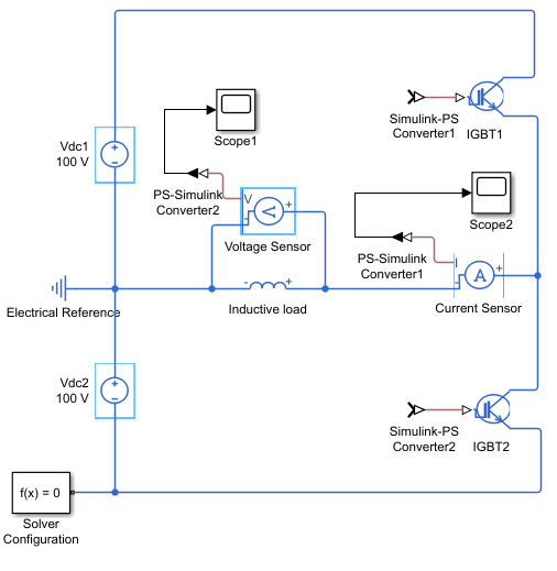
Build the Power Circuit
The power circuit comprises a DC link, two semiconductor switches with their anti-parallel diodes, and an inductive load.
To build the power circuit:
Create a new model.
Add the blocks in this table. The Library Path column specifies the hierarchical path to each block.
Block
Purpose Library Path
Quantity
DC Voltage Source Provide a DC link Simscape > Foundation Library > Electrical > Electrical Sources 2
IGBT (Ideal, Switching) Model two semiconductor switches with their anti-parallel diodes and build the half-bridge Simscape > Electrical > Semiconductor & Converters
2
Inductor Model an inductive load Simscape > Foundation Library > Electrical > Electrical Elements 1
Electrical Reference Provide the ground connection for the electrical conserving ports Simscape > Foundation Library > Electrical > Electrical Elements 1
Voltage Sensor Measure the voltage across the load Simscape > Foundation Library > Electrical > Electrical Sensors 1
Current Sensor Measure the current that flows through the load Simscape > Foundation Library > Electrical > Electrical Sensors 1
Solver Configuration Define the solver settings that apply to all physical modeling blocks Simscape > Utilities 1
Simulink-PS Converter Convert an output physical signal to a Simulink signal Simscape > Utilities 2
PS-Simulink Converter Convert a Simulink input signal into a physical signal Simscape > Utilities 2
Scope Display the load voltage and the current wave Simulink > Commonly Used Blocks 2
Note
You can use the Simscape™ function
sscnewwith a domain type ofelectricalto create a Simscape model that contains these blocks:Simulink-PS Converter
PS-Simulink Converter
Scope
Solver Configuration
Electrical Reference
Rename and connect the blocks as shown in the diagram.
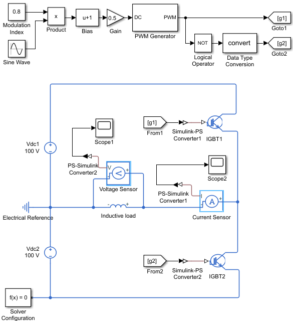
Build the Control System
The control system generates two pulse-width modulated (PWM) gate signals that
control the switching behavior of the two IGBT blocks. If the gate signal value is
equal to 1, the IGBT (Ideal, Switching) block turns on. If the
gate signal value is equal to 0, the block turns off.
To build the control system:
Add the blocks in this table to the model. The Library Path column specifies the hierarchical path to each block.
Block
Purpose Library Path
Quantity
Sine Wave Generate a sinusoidal signal that represents a unit sinusoidal modulation wave Simulink > Sources 1 Constant Define the sinusoidal pulse-width modulation index Simulink > Sources 1 Product Obtain the sinusoidal modulation wave by multiplying the unit sinusoidal wave by the modulation index Simulink > Math Operations 1
Bias Perform calculation to obtain the duty cycle signal Simulink > Math Operations 1
Gain Simulink > Math Operations 1
PWM Generator Generate the PWM gate signal for the IGBT1blockSimscape > Electrical > Control > Pulse Width Modulation 1
Logical Operator Obtain the complementary PWM gate signal for the IGBT2blockSimulink > Logic and Bit Operations 1
Data Type Conversion Convert the input Boolean signal to double signal Simulink > Signal Attributes 1
Goto Pass the input PWM gate signal to the corresponding From block Simulink > Signal Routing 2
From Receive a PWM gate signal from the corresponding Goto block and pass the signal as an output Simulink > Signal Routing 2
Rename and connect the blocks as shown in the diagram.
Specify Model Parameters
Specify these parameters to represent the behavior of the system components:
Model Setup Parameters
These blocks specify model information that is not specific to a particular block:
Solver Configuration
Electrical Reference
As with Simscape models, you must include a Solver Configuration block in each topologically distinct physical network. This example has a single physical network, so use one Solver Configuration block with the default parameter values.
You must include an Electrical Reference block in each Simscape Electrical™ network. This block does not have any parameters.
Power Circuit Parameters
Specify these parameters to represent the behavior of the power circuit components:
Set the Constant voltage parameter of the two DC Voltage Source blocks to
100.Set the parameters of the two IGBT (Ideal, Switching) blocks:
Main settings
Forward voltage, Vf —
0.8On-state resistance —
0.001Off-state conductance —
1e-5Threshold voltage, Vth —
0.5. With this value, the IGBT switches on when the value at the input port is equal to1and it switches off when the value at the input port is equal to0.
Integral Diode settings
Integral protection diode —
Protection diode with no
                                                dynamics
Forward voltage —
0.8On resistance —
0.001Off conductance —
1e-5
Set the parameters of the Inductor block:
Inductance —
0.005Series resistance —
1Parallel conductance —
0
Control System Parameters
Specify the following parameters to get the PWM gate signals for the
IGBT1 and IGBT2 from a sinusoidal
modulation wave:
In the Constant block, set the Constant value parameter to
0.8.To generate a unit sinusoidal modulation wave, set the parameters of the Sine Wave block:
Amplitude —
1Bias —
0Frequency (rad/sec) —
2*pi*60Phase (rad) —
0Sample time —
0
In the Bias block, set the Bias parameter to
1.In the Gain block, set the Gain parameter to
0.5.Set the PWM Generator block parameters:
Carrier counter —
Up-DownTimer period (s) —
1/2/2000Phase delay (s) —
0Sample time —
0
In the Logical Operator block, set the Operator parameter to
NOT.
The sinusoidal modulation wave is equal to To change the modulation wave, modify the modulation index, frequency, and phase values.
The PWM Generator block cannot receive the modulation wave as an input, because it must be a duty cycle. To obtain the duty cycle from the modulation wave, this example uses this equation:
where D is the duty cycle and M is the modulation wave. The Bias and Gain blocks of the control system implement this calculation.
The output PWM gate signal from the PWM Generator block controls the
IGBT1 block. The Logical Operator block implements the
complementary PWM gate signal that controls the IGBT2 block. The
value of the Timer period (s) parameter of the PWM Generator
block is equal to 1/2/2000, which means that the switching
frequency is equal to 2
kHz.
The Goto blocks and From blocks implement the connection between the generated PWM gate signals and the two IGBT (Ideal, Switching) blocks. Setting the Goto tag parameter in a Goto and From block to the same tag allows you to pass a signal from one block to another without connecting them.
Signal Display Parameters
Specify the parameters of the Scope block to display the output signals.
Double-click the Scope blocks and then click the View > Configuration Properties to open the Scope Configuration Properties dialog box. On the Logging tab, clear the Limit data points to last check box.
Configure the Solver Parameters
Configure the solver parameters to use a continuous-time solver. Simscape Electrical models only run with a continuous-time solver when you clear the Local Solver parameter of a Solver Configuration block. Use the Configuration Parameters dialog box to change the simulation end time, tighten the relative tolerance for a more accurate simulation, and remove the limit on the number of simulation data points Simulink® saves.
In the model window, select Modeling > Model Settings to open the Configuration Parameters dialog box.
In the left pane, click Solver:
Set Stop time to
4/60.Set Solver to
ode23t (Mod. stiff/Trapezoidal).Set Max step size to
1e-4.Set Relative tolerance to
1e-4.
Click OK.
For more information about configuring solver parameters, see Simulating an Electronic, Mechatronic, or Electrical Power System.
Simulate the Model and Analyze the Results
Run the simulation and plot the results. In the model window, select Simulation > Run.
To view the load voltage and current, double-click the Scope blocks. You can do this before or after you run the simulation.
This figure shows the load current.

The next figure shows the load voltage.
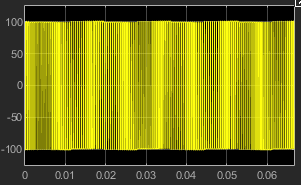
As expected, the load voltage is a PWM wave varying between -100 V and 100 V.
To view other simulation results, such as the current flowing through each IGBT (Ideal, Switching) block and its anti-parallel diode, use the Simscape Results Explorer. To enable the Simscape Results Explorer, first log the simulation data for all variables:
In the model window, select Modeling > Model Settings to open the Configuration Parameters dialog box.
In the left pane, click Simscape:
Set Log simulation data to
All.Select the Open viewer after simulation check box.
Clear the Limit data points check box.
Click OK.
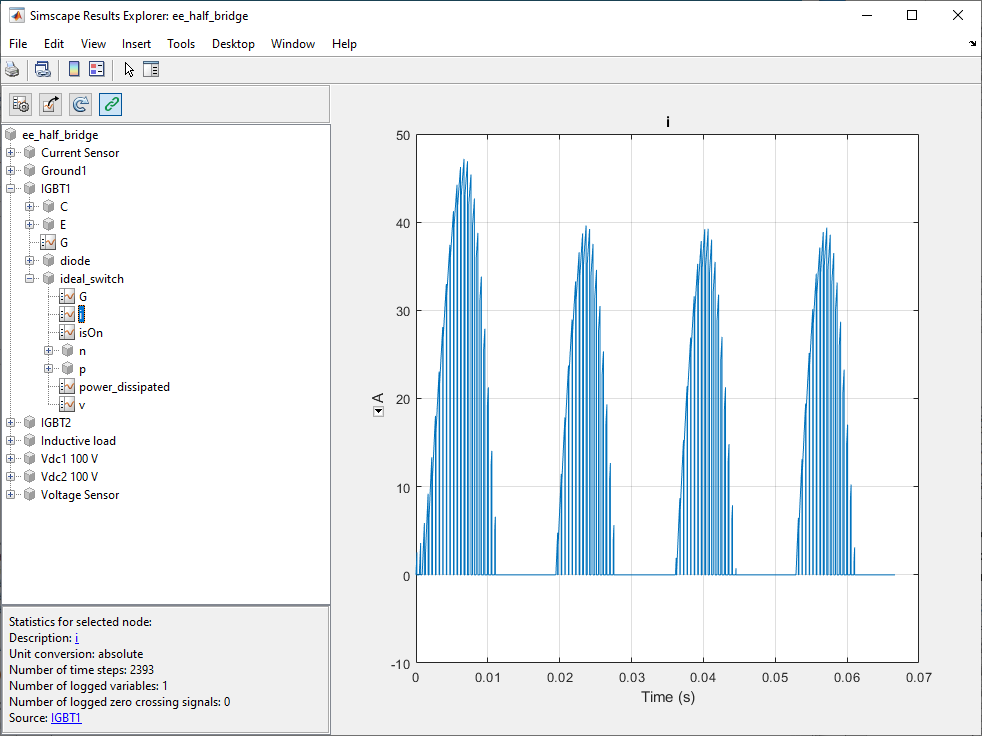
In the model window, select Simulation > Run to run the simulation. This figure shows the Simscape Results Explorer window that opens automatically.
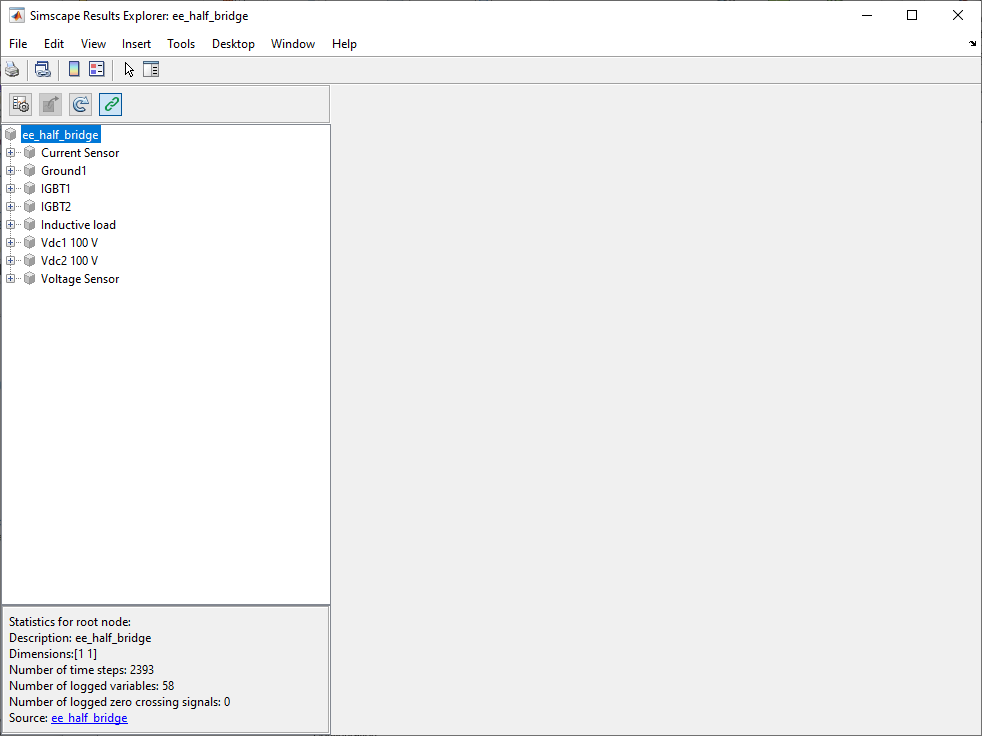
When you click a node in the left pane, the corresponding plots appear in the right
pane. For example, if you click the variable i in IGBT1 > ideal_switch, then the Simscape Results Explorer plots the current that flows through
the IGBT1 block in the half-bridge.
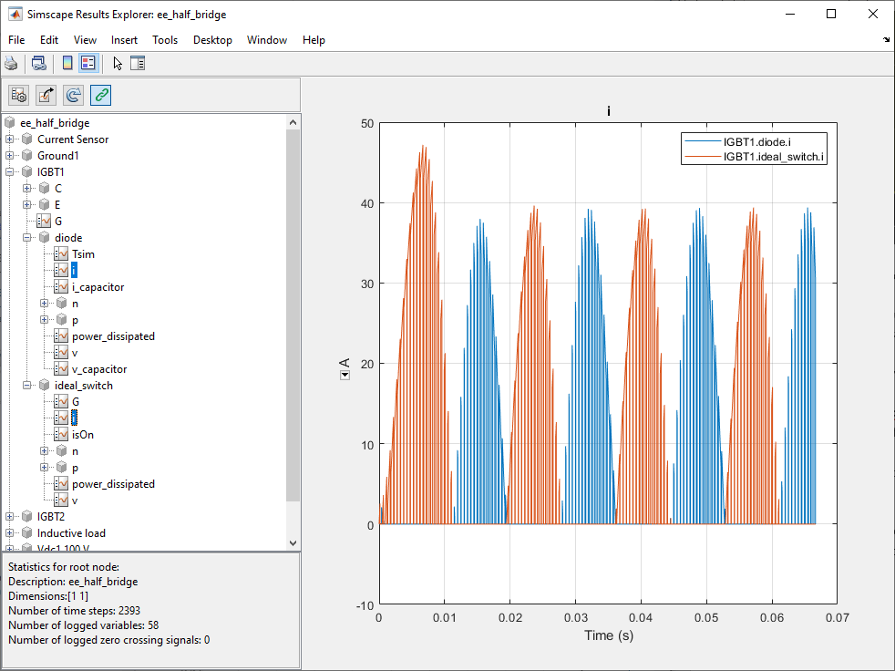
To select several variables for side-by-side plot comparison, press
Ctrl and click multiple variables. For example, check the
current that flows through the IGBT1 block and the current that flows
through the anti-parallel diode of the block:
For more information, see Simscape Results Explorer.
See Also
IGBT (Ideal, Switching) | Inductor