Connect Virtual Worlds and Models
After you create a virtual world and a Simulink® model, to have the virtual world interact with a dynamic system simulation, connect the model and the virtual world using Simulink 3D Animation™ blocks.
To use simulation data from a model to interact with a virtual world, include a VR Sink block in the model. For details, see Output Simulation Data to a Virtual World.
To use information from a virtual world to interact with a model, include a VR Source block in the model. For details, see Input Virtual World Data to a Model.
Simulating a Simulink model generates signal data for a dynamic system. To output data from the model to control and animate a virtual world, use a VR Sink block.
Open Tutorial Model Two
This example opens the tutorial model two, vrtut2, showing how to connect a Simulink® model to a virtual world.
open_system("vrtut2");Output Simulation Data to a Virtual World
This example shows how to use simulation data from a model to display a dynamic visualization of the simulation. The example simulates a plane takeoff and lets you view it in a virtual world. This example assumes that you are using the Simulink 3D Animation Viewer.
In the MATLAB® Command Window, type
openExample('vrtut2')A Simulink model opens without a Simulink 3D Animation block that connects the model to a virtual world.
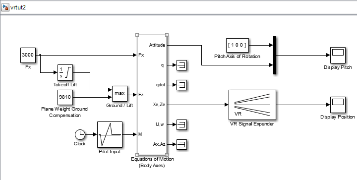
Simulate the model by clicking Run in the Simulate section of the Simulation tab in the Simulink toolstrip.
Observe the results of the simulation in the scope windows.
To the right of the model, left-click and type
VR Sink. In the dialog box, select the VR Sink block.Select a virtual world for the visualization of your simulation. Double-click the VR Sink block. Click Browse and select
vrtkoff.x3d.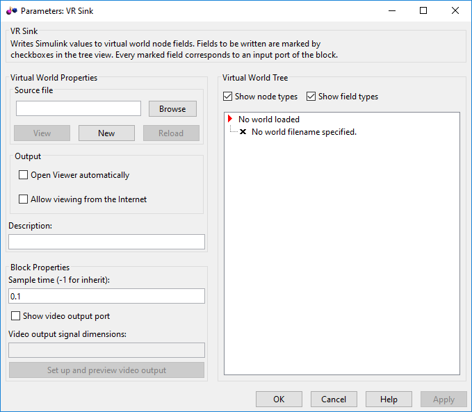
Associate a virtual world with the model. At the Source File text box, click the Browse button. The Select World dialog box opens. Select the file
vrtkoff.x3dand click OK.In the Description text box, examine the brief description of the model. This description appears on the list of available worlds served by the Simulink 3D Animation server.
Select the Open Viewer automatically parameter and click Apply. The VR Sink dialog box displays the virtual scene node tree, showing the structure of the associate virtual world.
Expand the
Plane (Transform)node.The list of characteristics of the plane can be driven from the Simulink interface. This model computes the position and the pitch of the plane.
In the
Plane (Transform)tree, select thetranslationandrotationfields, which represent the position and the pitch of the plane, respectively. Click OK.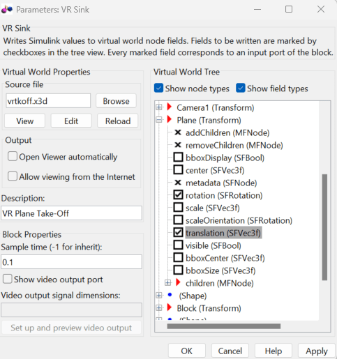
In the Simulink diagram, the VR Sink block is updated with two inputs.

The first input is
Plane rotation. Define the rotation with a four-element vector. The first three numbers define the axis of rotation. In this example, it is [1 0 0] for the x-axis (see thePitch axisblock in the model). The pitch of the plane is expressed by the rotation about the x-axis. The last number is the rotation angle around the x-axis, in radians. The rotation is in terms of the orientation of the object in space, relative to its parent node.In the Simulink model, connect the line going to the Scope block labeled
Display Pitchto thePlane rotationinput.The second input is
Plane translation. This input describes the position of the plane in the virtual world. This position consists of three coordinates, x, y, z. The connected vector must have three values. In this example, the runway is in the x-z plane (using the VR Signal Expander block). The y-axis defines the altitude of the plane.In the Simulink model, connect the line going to the Scope block labeled
Display Positionto thePlane translationinput.Remove the Scope blocks. Your model looks similar to the figure shown.
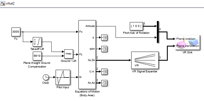
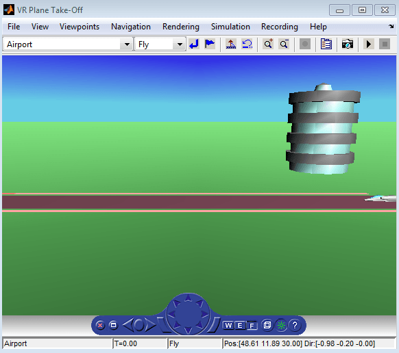
Double-click the VR Sink block. A viewer window containing the virtual world of the plane opens.
Tip
When you next open the model, the associated virtual scene opens automatically. This behavior occurs even if the Simulink 3D Animation block associated with the virtual scene is in a subsystem of the model.
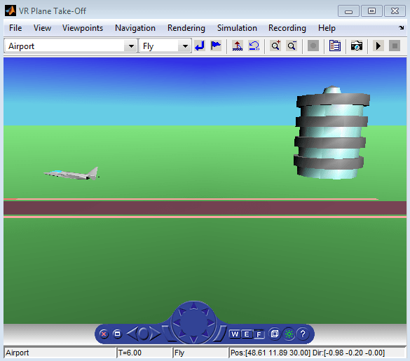
Run the simulation. In the Simulink 3D Animation Viewer, from the Simulation menu, click Run.
A plane, moving right to left, takes off.
Input Virtual World Data to a Model
You can use a VR Source block to provide interactivity between the virtual world and the simulation of a Simulink model. The VR Source block registers user interactions with the virtual world and passes that data to the model to affect the simulation of the model. The VR Source block reads values from virtual world fields specified in the block dialog box and inputs their values to a model. Using the block in this way, you can:
Use sensor data from a virtual world to control a simulation.
Provide interactivity between user navigation and interaction in a virtual world and the simulation of the model.
Have a simulation react to virtual world events, such as time ticks or outputs from scripts.
Use static information from the virtual world, such as the size of a box, to control a simulation.
For example, you can define setpoints in the virtual world, so that the user can specify the location of a virtual world object interactively. The simulation then responds to the changed location of the object. The VR Source block can read into the model events from the virtual world, such as time ticks or outputs from scripts. The VR Source block can also read into the model static information about the virtual world (for example, the size of a box defined in the virtual world 3D file).
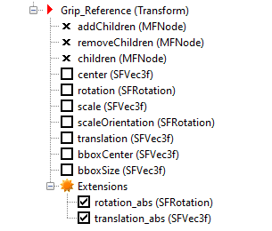
To use global coordinates for a virtual world object, include a
Transform node in that object. Open a second viewer window by
double-clicking the VR Source block. In the second viewer window (which
can overlap the first window), select Simulation > Block Parameters. For the Transform node of the object, select in the
Extensions branch one or both of these Simulink
3D Animation extensions for converting rotation and translation values into global
coordinates: rotation_abs and translation_abs.
For additional information about using the VR Source block and other approaches for provide interactivity in the model, see Use Sensors.
Change the Associated Virtual World
You can associate a different virtual world with a Simulink model or connect different signals.
After you associate a virtual world with a Simulink model, you can select another virtual world or change signals connected to the virtual world.
Double-click the VR Sink block in the model. The viewer opens.
Open the Block Parameters dialog box of the VR Sink block by selecting Simulation > Block Parameters.
At the Source File text box, click the Browse button. Select another source file and click OK. In the VR Sink dialog box, click Apply.
A virtual scene tree appears on the right side, associating a different virtual world with the model.
Expand the
Plane (Transform)node.The
Plane Transformtree expands. Now you can see what characteristics of the plane you can drive from the Simulink interface. This model computes the position.In the
Plane Transformtree, select thetranslationfield check box. Clear therotationfield check box. Click OK.The VR Sink block is updated and changes to just one input, the
Plane translation. The VR Sink block is ready to use with the new parameters defined.Verify that the correct output is connected to your VR Sink block. Connect the output from the VR Signal Expander is connected to the single input.

In the Simulink 3D Animation Viewer, from the Simulation menu, run the simulation again and observe the simulation.
See Also
Functions
vredit|vrlib|vrjoystick|vrspacemouse
