Main Content

ModuleAssembly (Generated Block)

Generated Simscape model of battery module assembly

Since R2022b

  • ModuleAssembly custom block

Description

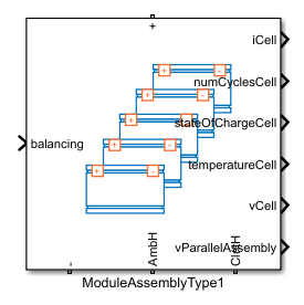
The ModuleAssembly block is a custom generated subsystem model of a battery module assembly. You can create this Simscape™ subsystem by using the buildBattery function with a ModuleAssembly object as an input argument. The ModuleAssembly subsystem block is inside the Simulink library that you specify in the LibraryName argument of the buildBattery function.

Note

To allow for structural changes and further customization, when you add the ModuleAssembly (Generated Block) masked library block from the parent library to a Simulink® model, the linked block does not contain the link or path to the parent library block. If you modify any of the battery structural properties, such as NumSeriesAssemblies or NumParallelCells, you must rebuild the original parent library and copy the block in your model again.

For more information about parent and linked blocks, see Linked Blocks.

The ModuleAssembly subsystem model comprises six major sections.

  • The Battery Modules section displays all the Module subsystems defined in the Module object. This section contains all the series and parallel electrical circuit connections between the modules, as well as the additional connections to the main electrical terminals and the module-to-thermal boundary conditions. If you require additional non-module resistances, then the function adds and connects two additional electrical resistors here.

  • The Output signals section groups the output of each Module block into a single multiplexed output signal for the ModuleAssembly subsystem.

  • The Thermal Boundary Conditions section contains the thermal boundary conditions for each Module block. The buildBattery function adds a connector port from the thermal domain and routes it to every Module subsystem according to the specified thermal boundary conditions. This section is optional and only appears if you define an ambient or coolant thermal path in the ModuleAssembly object.

  • The Balancing Signals section contains the routing of the cell balancing control signal from the battery management system to every Module subsystem. Selector blocks route the correct elements of the control signal to their corresponding ParallelAssembly blocks inside the modules.

  • The Coolant Thermal Liquid section contains the thermal liquid network manifold for the coolant that circulates inside the battery cooling plates. This section is optional and only appears if you define a cooling plate in the ModuleAssembly object.

  • The Cell Outputs section groups each output of the cell model block into a corresponding multiplexed output signal for the ModuleAssembly subsystem.

Battery Modules

This figure shows the Battery Modules section for a ModuleAssembly subsystem made of two battery modules.

Output Signals

This figure shows the Output Signals section for a ModuleAssembly subsystem made of two battery modules.

Thermal Boundary Conditions

This figure shows the Thermal Boundary Conditions section for a ModuleAssembly subsystem made of two battery modules.

Balancing Signals

This figure shows the Balancing Signals section for a ModuleAssembly subsystem made of two battery modules.

Coolant Thermal Liquid

This figure shows the Coolant Thermal Liquid section for a ModuleAssembly subsystem made of two battery modules.

Examples

Ports

Input

expand all

Switch control port for the balancing strategy, specified as a scalar.

Dependencies

To enable this port, set the BalancingStrategy property of the ModuleAssembly object to "Passive". Alternatively, set the BalancingStrategy property to "Passive" inside the parent object of which the ModuleAssembly object is a subcomponent.

Output

expand all

Note

The names of the output ports depend on the block you have specified in the CellModelOptions property of the underlying Cell object that constitutes this module assembly.

The names of the output ports in this page refer to a Cell object with the Battery (Table-Based) block as the cell component model block. If you specify a custom block for the cell component model, the names of the output ports might differ.

Note

The output ports of this block depend on the Simscape cell model block you used to create the battery object associated with this block. If the Simscape cell model block has output ports, the Battery Builder forwards these output ports to all the parent generated blocks of which the battery object is a subcomponent.

For example, if you create a custom Simscape cell model block with a Voltage output port and eventually use it to create this block, then this block has a Voltage output port. For more information about custom cell model blocks, see the CellModelBlockPath property of the CellModelBlock object.

Current at the cell level. The original signal units from the Module block are Amperes. The size of this signal is equal to the total number of electrical models in the system.

Cell-level number of cycles related to battery aging. The original signal units from the Module block are unitless. The size of this signal is equal to the total number of electrical models in the system.

State of charge at cell level. The original signal units from the Module block are unitless and the value typically varies between 0 and 1. The size of this signal is equal to the total number of electrical models in the system.

State of charge at the parallel assembly level. The original signal units from the Module block are unitless and the value typically varies between 0 and 1. The size of this signal is equal to the total number of parallel assemblies in the module assembly.

Temperature at the cell level. The original signal units from the Module block are Kelvin. The size of this signal is equal to the total number of electrical models in the system.

Dependencies

To enable this port, enable the thermal port of the cells that comprise the pack. To model the thermal port of the cells, in the CellModelBlock property of the cells, set the thermal_port parameter of the BlockParameters property to "Model".

Voltages at the cell level. The original signal units from the Module block are volts. The size of this signal is equal to the total number of electrical models in the system.

Voltages at the parallel assembly level. The original signal units from the Module block are volts. The size of this signal is equal to the total number of parallel assemblies in the module assembly. Use this signal as an input to the battery management system (BMS) blocks of Simscape Battery.

Since R2023a

Vector that contains the plate temperature, the fluid pressure drop, and the fluid temperature change of each cooling plate in the model. The size of this port depends on the number of cooling plates in the model.

Dependencies

To enable this port:

  • The ModuleAssembly object must not be a subcomponent of a Pack object.

  • Set the CoolingPlate property of the ModuleAssembly object to either "Top" or "Bottom".

Since R2024b

State of charge at cell level, specified as a scalar or vector.

Dependencies

To enable this port, use the Battery (Table-Based) block as the component model block for the Cell child object of this block and enable the SOC port.

Conserving

expand all

Electrical conserving port associated with the positive terminal of the battery module assembly.

Electrical conserving port associated with the negative terminal of the battery module assembly.

Thermal conserving port associated with the ambient thermal path.

Dependencies

To enable this port, set the AmbientThermalPath property of the ModuleAssembly object to "CellBasedThermalResistance". Alternatively, set the AmbientThermalPath property to "CellBasedThermalResistance" inside the top-level parent object of which the ModuleAssembly object is a subcomponent.

Thermal conserving port associated with the coolant thermal path.

Dependencies

To enable this port, set the CoolantThermalPort property of the ModuleAssembly object to "CellBasedThermalResistance". Alternatively, set the CoolantThermalPath property to "CellBasedThermalResistance" inside the top-level parent object of which the ModuleAssembly object is a subcomponent.

Note

If you set the CoolingPlate property to either "Top" or "Bottom" inside the ModuleAssembly object or inside the top-level parent object of which the ModuleAssembly object is a subcomponent, then this port is not enabled.

Since R2023a

Thermal conserving port used to connect the top side of the module assembly with a cooling plate. The size of this port depends on the total number of battery models in the system.

Dependencies

To enable this port:

  • The ModuleAssembly object must be a subcomponent of a Pack object.

  • Set the CoolingPlate property of the ModuleAssembly or the parent Pack object to "Top".

Since R2023a

Thermal conserving port used to connect the bottom side of the module assembly with a cooling plate. The size of this port depends on the total number of battery models in the system.

Dependencies

To enable this port:

  • The ModuleAssembly object must be a subcomponent of a Pack object.

  • Set the CoolingPlate property of the ModuleAssembly or the parent Pack object to "Bottom".

Since R2023a

Thermal fluid conserving port associated with the fluid that comes in each cooling plate of the model. The size of this port depends on the number of cooling plates in the model.

Dependencies

To enable this port:

  • The ModuleAssembly object must not be a subcomponent of a Pack object.

  • Set the CoolingPlate property of the ModuleAssembly object to either "Top" or "Bottom".

Since R2023a

Thermal fluid conserving port associated with the fluid that comes out of each cooling plate in the model. The size of this port depends on the number of cooling plates in the model.

Dependencies

To enable this port:

  • The ModuleAssembly object must not be a subcomponent of a Pack object.

  • Set the CoolingPlate property of the ModuleAssembly object to either "Top" or "Bottom".

Since R2024a

Electrical array-of-nodes conserving port associated with the positive terminals of the parallel assemblies inside this module assembly. Each element of this array corresponds to a positive terminal of a parallel assembly inside this module assembly.

Dependencies

To enable this port, set the BalancingStrategy property of the ModuleAssembly object to "External". Alternatively, set the BalancingStrategy property to "External" inside the Pack parent object of which the ModuleAssembly object is a subcomponent.

Since R2024a

Electrical array-of-nodes conserving port associated with the negative terminals of the parallel assemblies inside this module assembly. Each element of this array corresponds to a negative terminal of a parallel assembly inside this module assembly.

Dependencies

To enable this port, set the BalancingStrategy property of the ModuleAssembly object to "External". Alternatively, set the BalancingStrategy property to "External" inside the Pack parent object of which the ModuleAssembly object is a subcomponent.

Version History

Introduced in R2022b

expand all